


10
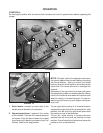
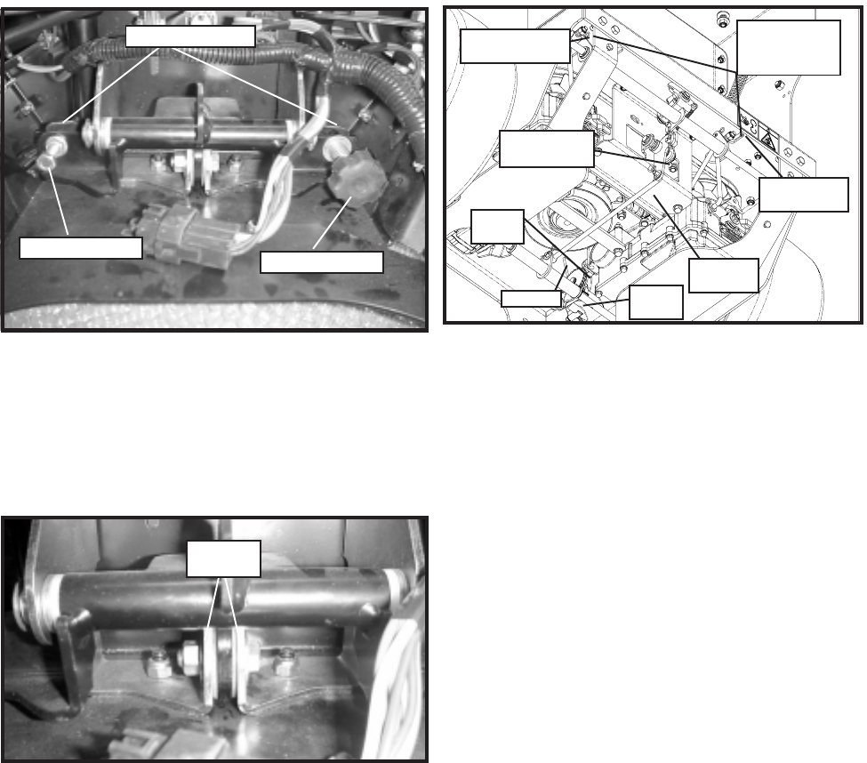
FIGURE 7
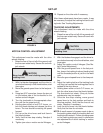
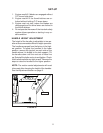
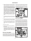
BYPASS ADJUSTMENT
If the mower will not free wheel with the brake/by-
pass lever in the bypass position, an adjustment
may be needed. Jack up the rear of the unit and
secure with jack stands. Remove the rear guard
on the back of the rear deck. (See Figure 7.) Place
the brake/bypass lever in the brake position. Us-
ing a 1/2” wrench, tighten the nyloc nut on the by-
pass linkage until the compression spring is fully
compressed. Move the brake/bypass lever into the
bypass position. Check the tires to verify that they
will turn. If they still will not turn, a brake adjust-
ment may be required. (See Brake Adjustment.)
NOTE: IF THE BYPASS ADJUSTMENT IS
MADE WITH THE BRAKE BYPASS LEVER IN
THE BYPASS POSITION, THE BRAKE POSI-
TION MAY NOT BE OBTAINABLE.
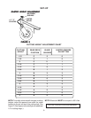
COMPRESSION
SPRING
BYPASS
ADJUSTMENT
NUTS
BRAKE
BELLCRANK
IZT BYPASS
LINKAGE
BRAKE
LINKAGE
BRAKE
COG
BRAKE
ARM
SWIVEL
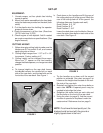
SET-UP
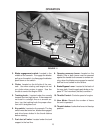
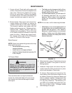
GROUND SPEED LEVER FRICTION
The ground speed lever has friction washers to
adjust the tension of the lever. To adjust, use two
9/16” wrenches and tighten or loosen the bolt and
nut on each side of the friction plate. See Figure 6.
FIGURE 6
BRAKE ADJUSTMENT
Jack up the rear of the unit and secure with jack
stands. Remove the rear guard on the back of the
rear deck. Remove the hairpin and washer from
the rear of the brake linkage. See Figure 7. Place
the brake/bypass lever in the brake position. Pull
back on the brake linkage. Verify that the IZT brake
arms are fully seated in the brake cogs. (The tires
may need to be rotated slightly to seat the brakes.)
Turn the linkage in the swivel until the linkage just
slides in the hole in the brake bell crank. Replace
the washer and hairpin. Verify that the brakes en-
gage.
TRACKING BOLT
TRACKING PLATE
TRACKING KNOB
FIGURE 5
FRICTION
PLATES
INTERLOCK SAFETY SYSTEM
The interlock modules function is to prevent the
engine from starting if the blades are engaged and/
or the driver levers are not locked in the thumb
latches. It also causes engine shutdown if the op-
erator removes hands, or attempts to leave the
operator position while the blades are engaged or
the drive levers are not locked in the thumb latches.
After the engine starts, the operator must hold ei-
ther the left or right O.P. lever down before engag-
ing the blades or unlocking the thumb latches. If
neither O.P. lever is held, the engine will kill. Check
the function of the safety electrical system on a
regular basis.