UNPA(:kING AND SIT-UP
1. BefQre assembling your Snow Thrqwer be sUl'e all har<J-
ware, parts, and instructions have been removed from
the c~rtol),
2 Assen1ble: right and left !1andle tubes to the unit with
bolts, lockwa~~er, and flat w&shers~ po not tighten,3.
Assemble han!:ile pane.! assembly to the under side of
right and left hanpte tubes and seCIJre with tour slO'tted
hex head bo/:ts and lock nuts. Tighteli all bolts on the
handle tJ9semb'Jv.4.
Assemble c;hu,te ~djustl'nent sh~ft through hole in 1t\e
hi')ndle p,anel and into universal Joint looated on left
hand side of ~he trame. Align hole in universAl j9fnt With
the hole in CfJute adjiJstment shaft and dtive spring'pln
through the n6tes;5.
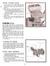
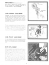
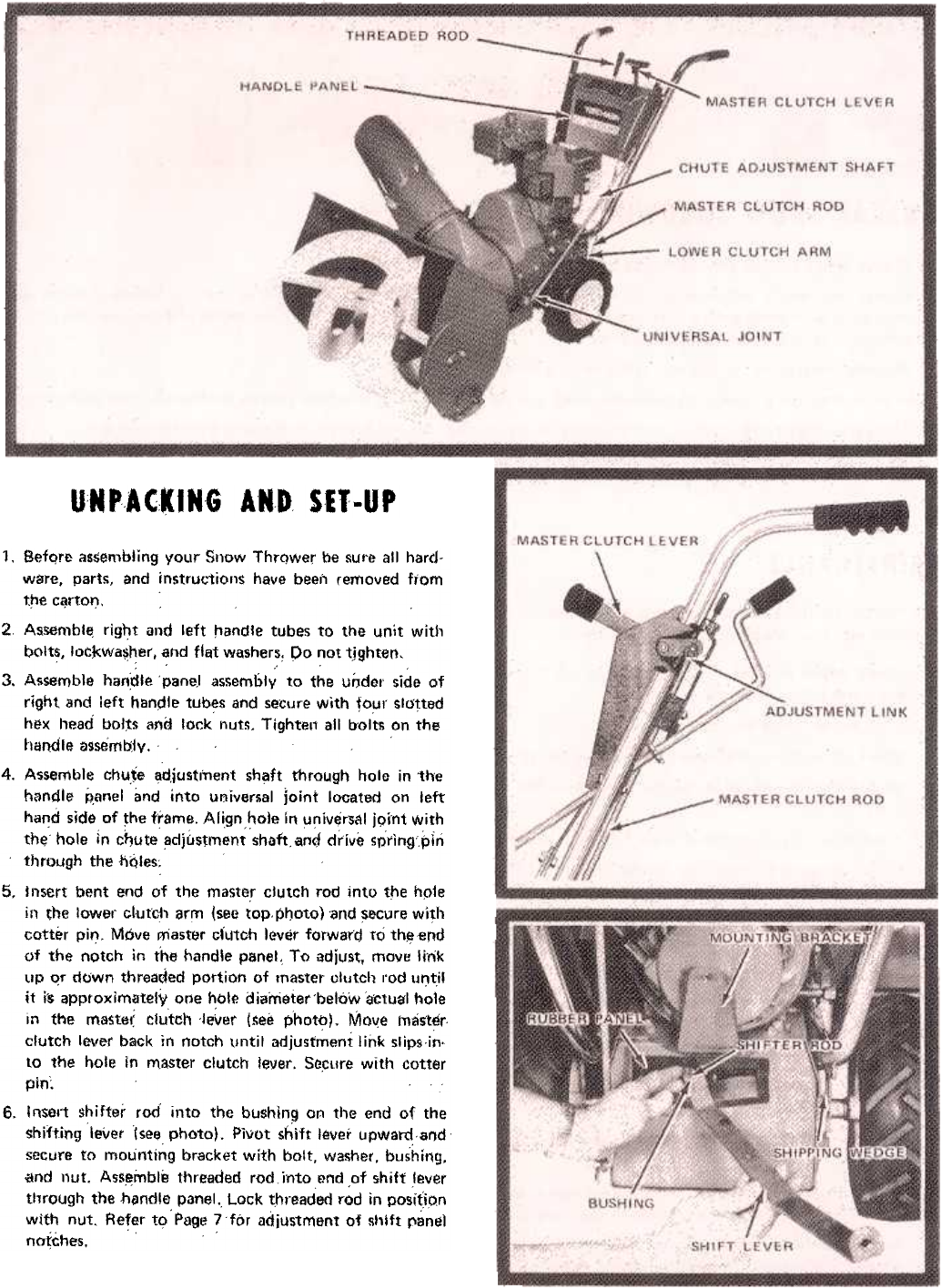
Insert bent end of the master clutch rod into tt1e hple
il'l the lower C!utC!1 arm (see top,Pt:Joto) 'and ~&cure with
cotter pin. Move master ciutch lever forward to th~end
of the notch in the handle panel. To adjust, mOIl!! Irnk
up O;f down threaded portion of master ol\Jtch rod ur:-til
it i-s approximately one hole diameter'below ~CtLJgl hole
in the mastet: clutch 'j~ver (see photo). Move tncist~r
clutch lever back in notch until adjustment link Slips in.
to the hole in master clutch lever. Socure with cotter
pin:6.
Insert shifter rod into the bLJshin~ on the end of the
shifting lever (see photo). Pivot shift lever upward,and
secure to mounting bracket with bolt, wa!\her, bushing,
.and nut. Assemble threaded rod rnto end ,of shift .lever
tllrough the h~ndlE) panel. Lock threaded rod in posi(ion
wIth nut. Refer tl;>' Page 7 for adjustment of sl'ift panel
n(J~ches,


