


6
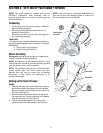
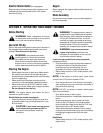
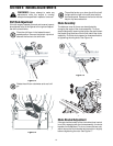
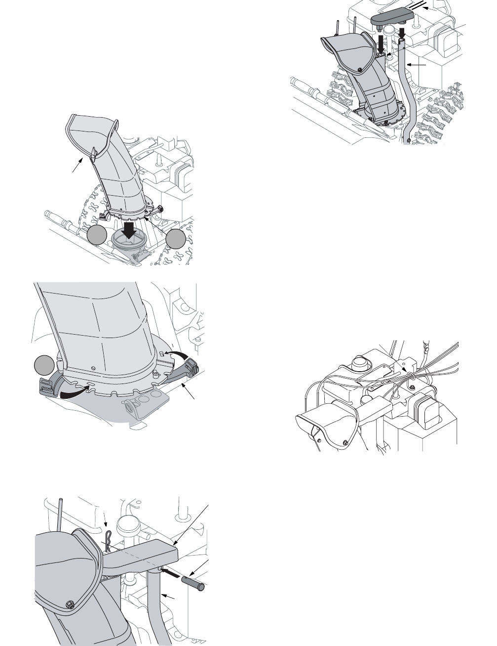
Chute Assembly (all models)
1. Apply a light lubricant (i.e. 3-in-1 oil) to the base of
the chute assembly.
2. Place the chute assembly on the lip of the chute
adapter. See Figure 3
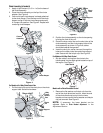
3. One end of each chute keeper is already attached
to the chute flange. Pivot the free end of the chute
keeper to align it with the chute flange and push it
till it snaps into position. See Figure 4. Repeat with
remaining chute keepers.
Figure 3
Figure 4
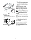
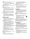
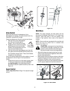
For Models with 4 Way Chute Control Box
1. Pull the hairpin clip out of the clevis pin on the chute
support tube. Save this hardware.
Figure 5
Figure 6
2. Position the chute assembly so the chute opening
is facing the front of the unit.
3. Place the chute control box on the short tube of the
chute assembly and the chute support tube of the
chute assembly as shown in Figure 6, cables
should be towards the operator.
4. Insert the clevis pin, earlier removed, through the
holes on the chute control box and chute support
tube. Secure with the hairpin clip. See Figure 5.
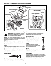
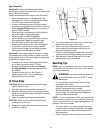
For Models with 2Way Chute Control
1. Slip the cables, running from the chute to the
handle panel into the cable guide located on top of
the engine. See Figure 7 .
Figure 7
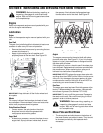
Models with a Chute Directional Control
1. Remove the flat washer and hairpin clip from the
end of the chute directional control. Insert the end
of the chute directional control into the lower
bracket and secure with the flat washer and hairpin
clip just removed. See Figure 8.
NOTE: If necessary, the lower bracket can be
adjusted. Refer to Chute Bracket Adjustment. in the
Adjustment Section.
Chute
Assembly
1
2
Chute
Assembly
3
Chute Keeper
Chute Support
Tube
Hairpin Clip
Clevis
Pin
4 Way
Chute
Control
Box
Chute Support
Tube
Short
Tube
Cables
Cable Guide