


17
• To remove skid shoes, remove the four carriage
bolts and hex flange nuts which secure them to the
snow thrower. Reassemble new skid shoes with the
four carriage bolts (two on each side) and hex
flange nuts. Refer to Figures 19 and 21.
• To remove shave plate, remove the carriage bolts,
cupped washers and hex nuts which attach it to the
snow thrower housing. Reassemble new shave
plate, making sure heads of carriage bolts are to
the inside of housing. Tighten securely.
Replacing Belts
Check the condition of both auger belt and drive belt
every 25 hours of snow thrower operation. Replace if
either shows signs of wear and tear.
Auger Belt
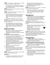
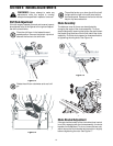
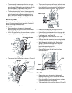
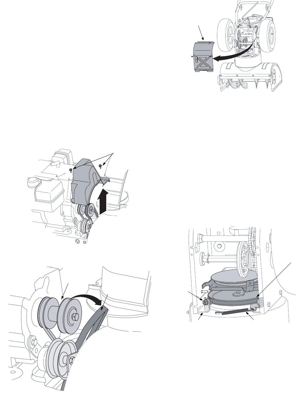
• Remove belt cover by removing the two self-
tapping screws that secure it to the snow thrower
housing. See Figure 22.
• •Drain the gasoline from the snow thrower, or place
a piece of plastic under the gas cap.
Figure 22
• Take auger belt off the pulley as shown in Figure 23
Figure 23
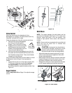
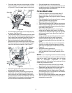
• Tip the snow thrower up and forward, so that it rests
on the housing. Remove two self-tapping screws
from the frame cover underneath the snow thrower
and move the frame cover away. See Figure 24.
Figure 24
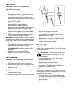
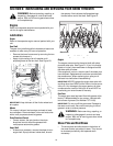
• Half turn shoulder screw and slide it out of the
mounting bracket. See Figure 25.
• Unhook spring to release tension on the auger belt.
Remove old belt and replace with new belt installing
it on the groove. See Figure 25.
• Wrap auger belt around the auger pulley. See
Figure 25.
• Re-insert shoulder screw into the mounting bracket
and tighten to secure.
• Wrap auger belt behind the idler. Reattach the
spring to the bolt where it was earlier secured.
• Re-install frame cover and flip the snow thrower
back to the operating position.
• Wrap auger belt around the engine pulley.
• Re-install belt cover with self-tapping screws
removed before.
Figure 25
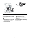
Drive Belt
• Remove belt cover by removing the two self-
tapping screws that secure it to the snow thrower
frame. See Figure 22.
• Drain the gasoline from the snow thrower, or place
a piece of plastic under the gas cap.
• Take auger belt off the pulley as shown in Figure 23
Self-tapping Screws
Engine
Pulley
Auger
Belt
Frame Cover
Shoulder
Screw
Spring
Auger
Pulley
Mounting Bracket