


18
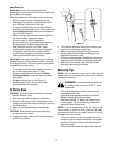
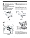
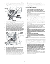
• Push idler away from the chute and insert a Philips
head screwdriver in the hole on the idler as shown
in Figure 26. This will release tension on drive belt.
Figure 26
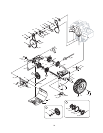
• Pull drive belt out and away from the engine pulley
to remove. See Figure 26.
• Tip the snow thrower up and forward, so that it rests
on the housing. Remove two self-tapping screws
from frame cover underneath the snow thrower and
move the frame cover away. Refer to Figure 24.
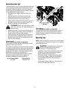
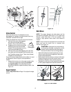
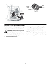
• Back out the stop bolt to create sufficient gap
between the friction wheel disc and the drive pulley.
Pull the drive belt from around the drive pulley and
clear it off the friction wheel disc. See Figure 27.
Figure 27
• Now moving to the other side of the snow thrower ,
slide the belt off the crankshaft.
• Replace with new belt, first sliding it through the
crank shaft, then working it around the groove of
the drive pulley and finally wrapping it around the
engine pulley from where the old belt was removed.
Once the belt is firmly placed on the pulleys, make
sure to remove the screwdriver from the idler.
• Re-install auger belt on the engine pulley.
• Re-attach frame cover and put the equipment back
to operating position. Re-attach belt cover with two
self-tapping screws removed earlier.
Friction Wheel Rubber
• Check the rubber on the friction wheel after 25
hours of operation, and periodically thereafter.
Replace the rubber if any signs of wear or cracking
are found.
• Drain the gasoline from the snow thrower, or place
a piece of plastic under the gas cap.
• Move shift lever to the R2 position.
• Tip the snow thrower so that it rests on the housing.
• Remove two self-tapping screws from frame cover
underneath the snow thrower and move the frame
cover away. See Figure 24.
• Remove the right-hand wheel by removing the
screw and bell washer which secure it to the axle.
• Locate the hex shaft and snap ring on the right side
of the snow thrower frame, about two inches from
the wheel axle.
• Using a suitable tool, carefully remove the outer E-
ring which secures the hex shaft to the snow
thrower frame and lightly tap the shaft’s end to
dislodge the ball bearing from the right side of the
frame.
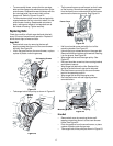
• Slide the hex shaft downward and to the left while
carefully un-meshing the lower gears on the hex
shaft from the upper gears on the wheel axle. See
Figure 28.
• Set the hex shaft’s gears aside.
• Carefully remove the inner E-ring from the hex
shaft and slide the friction wheel assembly off the
hex shaft.
NOTE: If you’re replacing the friction wheel assembly
as a whole, discard the worn part and slide the new part
onto the hex shaft. Follow the steps above in reverse
order to reassemble components. If you’re
disassembling the friction wheel and replacing only the
rubber ring, proceed as follows:
• Remove the four screws from the friction wheel
assembly and remove the bonded friction wheel.
• Reassemble new bonded friction wheel rubber to
the friction wheel assembly, turn each screw
approximately 2 turns in order shown in Figure 29
until screws are tight. It is important for the rubber to
be assembled symmetrically.
• Slide the friction wheel assembly back onto the hex
shaft and follow the steps above in revers order to
reassemble components.
Engine
Pulley
Idler
Drive Belt
Auger Belt
Stop
Bolt
Drive Pulley
Friction
Wheel
Drive
Belt