


7
auger drive clutch grip against the left handle
completely.
3. If necessary, loosen the hex lock nut and thread
the cable in (for less slack) or out (for more slack)
as necessary. Recheck the adjustment. Tighten
the lock nut against the cable when correct
adjustment is reached.
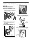
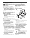
Traction Drive Clutch and Shift Lever
1. Tip the snow thrower forward so that it rests on
the auger housing.
2. Move the shift lever all the way forward to sixth
(6) position.
3. With the traction drive lever released, spin the
snow thrower wheels by hand. The wheels should
turn; however, you may feel some resistance.
4. Engage the traction drive clutch grip. The wheels
should no longer turn.
5. Now release the traction drive clutch grip, and
spin the wheels again.
6. Move the shift lever back to the fast reverse
position, then all the way forward again. There
should be no resistance in the shift lever, and the
wheels should turn.
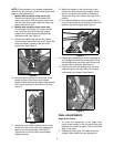
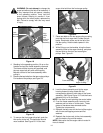
7. If you face resistance when moving the shift lever
or the snow thrower wheels stop when they
should not, loosen the lock nut on the traction
drive cable and unthread the cable one turn.
8. If the wheels can still be turned when you engage
the traction drive clutch grip, loosen the lock nut
on the traction drive cable and thread the cable in
one turn.
9. Recheck the adjustment and repeat adjustment
as necessary. Tighten the lock nut to secure the
cable when correct adjustment is reached.
NOTE: If you are not sure that you have reached
correct adjustment, refer to the Adjustment section on
page 11.
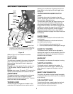
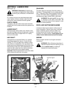
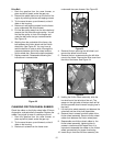
Skid Shoe
The space between the shave plate and the ground
can be adjusted. For close snow removal, place skid
shoes in the low position. Use middle or high position
when area to be cleared is uneven. See Figure 15 on
page 13.
1. Adjust skid shoes by loosening the four hex nuts
and carriage bolts and moving skid shoes to
desired position.
2. Make certain the entire bottom surface of skid
shoe is against the ground to avoid uneven wear
on the skid shoes.
3. Tighten nuts and bolts securely.
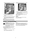
TIRE PRESSURE (Pneumatic Tires)
The tires are over-inflated for shipping purposes.
Check tire pressure and reduce to 15 to 20 psi.
NOTE: If the tire pressure is not equal in both tires,
the unit may pull to one side or the other.