


16
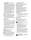
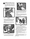
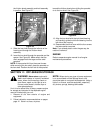
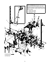
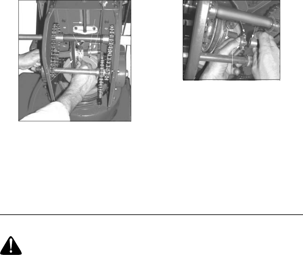
the friction wheel assembly and hold assembly
in position. See Figure 25.
Figure 25
11. Slide the hex shaft through the left side of the
housing and through the friction wheel
assembly.
12. Insert the hex shaft through the sprocket and the
spacer. See Figure 25. Make certain that the
chain engages both the large and the small
sprocket.
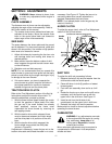
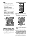
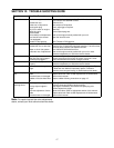
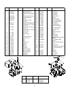
NOTE: If the sprocket fell from the snow thrower
while removing the hex shaft, place the sprocket on
the hex shaft. Position the hex hub of the sprocket
toward the friction wheel when sliding the sprocket
on to the hex shaft. See Figure 26.
Figure 26
13. Align the hex shaft with the right hand bearing
and carefully guide the left hand bearing into the
left side of the housing.
14. Reassemble the drive cover with the four screws
that were earlier removed.
Note: If you placed plastic under the gas cap, be
certain to remove it.
ENGINE
Refer to separate engine manual for all engine
maintenance procedures.
SECTION 11: OFF-SEASON STORAGE
WARNING: Never store engine with
fuel in tank indoors or in poorly ventilated
areas, where fuel fumes may reach an
open flame, spark or pilot light as on a
furnace, water heater, clothes dryer or
other gas appliance.
If unit is to be stored over 30 days, prepare engine
for storage as instructed in the separate engine
manual included with your unit.
1. Remove all dirt from exterior of engine and
equipment.
2. Follow lubrication recommendations on pages
page 12. Store in a clean, dry area.
NOTE: When storing any type of power equipment
in an unventilated or metal storage shed, care
should be taken to rust proof the equipment. Using a
light oil or silicone, coat the equipment, especially
any chains, springs, bearings and cables.
Shift Arm
Assembly
Pin
Friction
Wheel
Sprocket
Spacer
Spacer
Sprocket
Hex Hub
of Sprocket
Hex Shaft