


11
SECTION 8: ADJUSTMENTS
WARNING: Never attempt to clean chute
or make any adjustments while engine is
running.
CHUTE ASSEMBLY
The distance snow is thrown can be adjusted by
adjusting the angle of the chute assembly. Refer to
the Control section of this manual.
1. The remote chute control cables have been pre-
adjusted at the factory. Move the remote chute
lever on the control panel back and forward to
adjust angle of the chute asssembly.
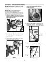
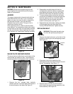
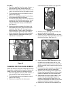
SKID SHOE
The space between the shave plate and the ground
can be adjusted. For close snow removal, place skid
shoes in the low position. Use middle or high position
when area to be cleared is uneven.
1. Adjust skid shoes by loosening the four hex nuts
and carriage bolts and moving skid shoes to
desired position.
2. Make certain the entire bottom surface of skid
shoe is against the ground to avoid uneven wear
on the skid shoes.
3. Retighten nuts and bolts securely.
NOTE: It is not recommended that you operate this
snow thrower on gravel as loose gravel can be easily
picked up and thrown by the auger causing an injury
or damage to the snow thrower.
4. If for some reason, you have to operate the
snow thrower on gravel, keep the skid shoe in
the highest position for maximum clearance
between the ground and the shave plate.
TRACTION DRIVE CLUTCH
Refer to the Final Adjustment section of the Set-Up
Instructions to adjust the traction drive clutch. To
check the adjustment, proceed as follows:
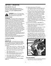
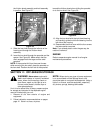
1. With the snow thrower tipped forward (be certain
to drain the gasoline or place plastic film under
the gas cap if the snow thrower has already
been operated), remove the frame cover
underneath the snow thrower by removing six
self-tapping screws.
2. With the traction drive clutch released, there
must be clearance between the friction wheel
and the drive plate in all positions of the shift
lever.
3. With the traction drive clutch engaged, the
friction wheel must contact the drive plate
(shown in Figure 22).
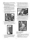
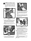
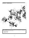
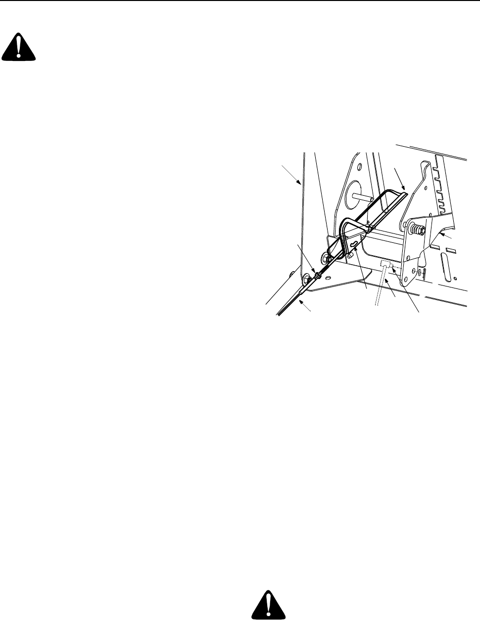
If adjustment is necessary, loosen the jam nut on the
traction drive cable and thread the cable in or out as
necessary. See Figure 12. Tighten the jam nut to
secure the cable when correct adjustment is
reached. Reassemble the frame cover.
NOTE: If you placed plastic under the gas cap, be
certain to remove it.
AUGER CLUTCH
To adjust the auger clutch, refer to Final Adjustment
section of Set-Up Instructions.
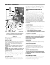
Figure 12
SHIFT ROD
To adjust the shift rod, proceed as follows.
1. Remove the hairpin clip and flat washer from the
shift handle under the handle panel.
2. Place shift lever in sixth (6) position or fastest
forward speed.
3. Push shift arm assembly down as far as it will
go.
4. Rotate the ferrule up or down on the shift rod as
necessary until the ferrule lines up with the
upper hole in the shift lever. See Figure 12.
5. Insert ferrule from the left side of the
snowthrower into the upper hole in shift lever.
6. Reinstall the hairpin clip and the washer.
Make certain to check for correct adjustment before
operating the snow thrower.
CARBURETOR
WARNING: If any adjustments are made
to the engine while the engine is running
(e.g. carburetor), keep clear of all
moving parts. Be careful of heated
surfaces and mufflers.
Minor carburetor adjustments may be required to
compensate for differences in fuel temperature,
altitude and load.
Clutch
Grip
Hex Jam Nut
(Thread
here)nut
Cable is straight
but not tight
Z Fitting
Shift
Rod
Ferrule
Shift
Handle
(Viewed from under the handle panel)
Handle
Panel