


65
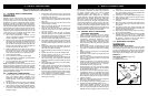
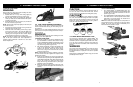
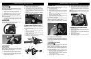
THE PUSH (PINCH-KICKBACK) AND PULL
REA
CTIONS
(Figure 2-4B)
A = Pull
B = Solid objects
C = Push
KICKBACK may occur when the NOSE or TIP of the guide
bar touches an object, or when wood closes in and pinch-
es the saw chain in the cut.
Tip contact in some cases may cause a lightning-fast
reverse reaction, kicking the guide bar up and back toward
the operator.
PINCHING the saw chain along the BOTTOM of the guide
bar may PULL the saw forward away from the operator.
PINCHING the saw chain along the TOP of the guide bar
may PUSH the guide bar r
apidly back toward the operator.
Any of these reactions may cause you to lose control of the
saw, which could result in serious personal injury.
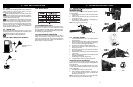
2-5. KICKBACK SAFETY LABELS
Your MTD Chain Saw is provided with a safety label locat-
ed on the air cleaner cover. This label, along with the safe-
ty instructions on these pages, should be carefully read
bef
ore attempting to operate this unit.
HOW TO READ SYMBOLS AND COLORS:
WARNING
Used to warn that an unsafe procedure should not be per-
formed.
RECOMMENDED
Recommended cutting procedures.
WARNING(Figure 2-5A)
1. Worst-case computed kickback angle.
2. Beware of kickback.
3. Do not attempt to hold saw with one hand.
4. Avoid bar nose contact.
RECOMMENDED
5. Hold saw properly with both hands.
GREEN
RED
The engine exhaust from this product contains chemi-
cals known to the State of California to cause cancer,
birth defects, or other reproductive harm.
WARNING
2-5A
2-4B
A
B
B
C
2-6. INTERNATIONAL SYMBOLS
W
ear head, e
y
e and hear
ing protection.
Wear gloves to protect your hands.
W
ear safety boots to protect against electric shock.
Read User Manual.
Use of these personal safety items is
highly recommended to reduce the risk
of accidental injury.
3 - ASSEMBLY INSTRUCTIONS
3-1. TOOLS FOR ASSEMBLY (MOST UNITS
ARE ASSEMBLED AT THE FACTORY)
You will need these tools to assemble your chain saw:
1. Combination wrench-screwdriver (contained in your
user’s kit or in lid of carry case).
2.
Heavy duty work gloves (user supplied).
3-2. ASSEMBLY REQUIREMENTS
Your new chain saw will require adjustment of chain, filling
the fuel tank with correct fuel mixture and filling the oil tank
with lubricating oil before the unit is ready for operation.
WARNING
DO NOT start saw engine until unit is properly prepared.
Read the entire user manual before attempting to operate
your unit. Pay particular attention to all safety precautions.
Your user manual is both a reference guide and handbook
provided to furnish you with general information to assem-
ble, operate and maintain your saw.
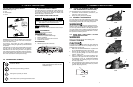
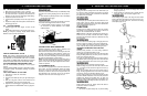
3-3. GUIDE BAR / SAW CHAIN / CLUTCH
COVER INSTALLATION
WARNING
Always wear protective gloves when handling chain.
TO INSTALL GUIDE BAR:
CAUTION
To ensure the bar and chain receive oil, ONLY USE THE
ORIGINAL STYLE BAR with the oil passage hole (A) as
illustrated above (Figure 3-3A).
1. Make sure the CHAIN BRAKE
®
lever is pulled back
into the DISENGAGED position (Figure 3-3B)
2. Remove the bar retaining nuts (B). Remove clutch
co
v
er (C) by pulling straight out, some force may be
required. (Figure 3-3C)
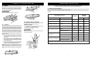
3. Using a screwdriver or the wrench supplied in the
user’s kit or in the upper half of the carrying case.Turn
the adjustment screw (D) COUNTERCLOCKWISE
until the TANG (E) (projecting prong) is to the end of
its travel (Figure 3-3D).
4.
Place the slotted end of the guide bar o
v
er the bar bolt
(F). Slide guide bar behind clutch drum (G) until the
guide bar stops (Figure 3-3E).
A
3-3A
3-3B
3-3C
C
B
3-3D
3-3E
E
G
F
2 - SAFETY PRECAUTIONS
D