


Installation and Configuration
User Signals
Release 3.1 31
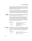
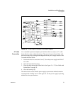
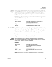
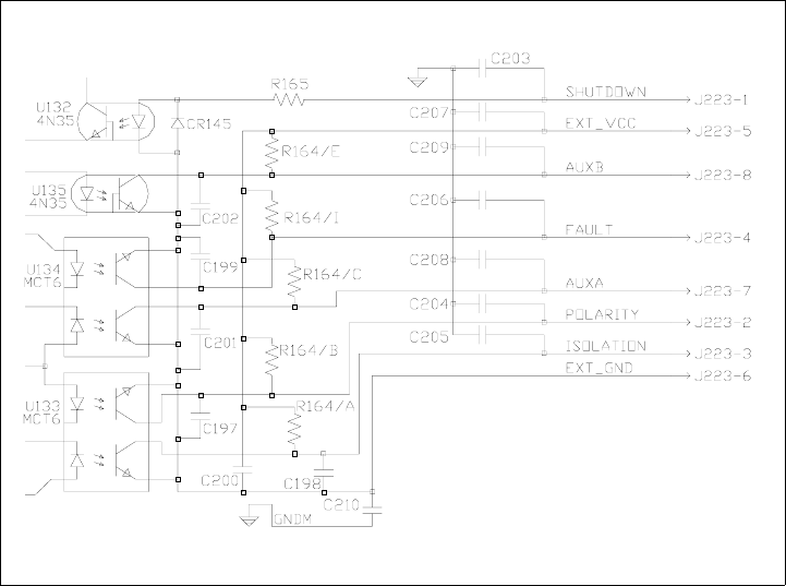
Figure 2.5 J7 User Signal Connector Circuit Block Diagram
J7 Cable
Connection
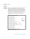
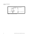
Use a standard 8-position telephone jack and data cable to connect to J7. Add a
ferrite block to reduce radiated emission. The one inch square ferrite block with
built-in housing clip is packaged and shipped with the power supply interface card.
To install the ferrite block:
1. Position the block no more than 5 cm (2") from the power supply end of the J7
user cable.
2. Open the ferrite block housing.
3. Loop the cable through the ferrite block. See Figure 2.6, “J7 User Cable with
Ferrite Block” on page 32.
4. Close the housing clip.
The ferrite block ensures that the power supply system meets radiated emission
requirement 89/336/EEC for CE mark approval. See the power supply's operating
manual for noise specifications.