


Installation and Configuration
Initial Inspection
22 Operating Manual for GPIB for XHR/XFR Series Power Supply
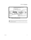
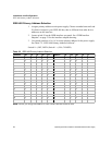
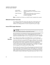
Figure 2.3 GPIB Interface PCB
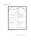
JUMPER SELECTION
J65 Local OVP control selection [closed] [default]. See page 28.
[open] Front Panel OVP Control.
J93 User TTL shutdown (S/D) selection [1-2] User TTL S/D line active low.
See page 31.
[2-3] [default] User TTL S/D line active high.
J103 Remote OVP Control Selection [closed] [default]. See page 28.
[open]
Note: All other jumpers are not user-selectable.
LED INDICATORS
CR89 Red Diagnostic LED Bus error or soft restart on Slave circuitry.
CR166 Red Diagnostic LED Soft restart on Master circuitry.
CR167 Green Diagnostic LED Bus error on Master circuitry.
See page 52.
EPROMS
U117 Slave EPROM See revision number stamped on EPROM.
U191 Master EPROM See revision number stamped on EPROM.