


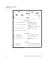

Installation and Configuration
User Signals
30 Operating Manual for GPIB for XHR/XFR Series Power Supply
User Signals
Connector J7
User Signals
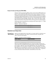
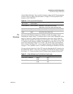
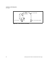
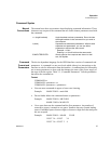
Auxiliary connector J7, located on the GPIB interface rear panel, provides several
signals to increase your operating control of the supply. These signals are
dependent on the operator's design and uses. The operation of the J7 signal requires
that you provide external Vcc and ground. Use a standard 8-position telephone jack
and data cable to connect to J7. To locate the connector, refer to the GPIB interface
subplate drawing in Figure 2.2, on page 21. See Figure 2.4, “User Signals J7
Connector” on page 30 for pin descriptions. The J7 outputs can sink a current of
5mA each. Figure 2.5, “J7 User Signal Connector Circuit Block Diagram” on page
31 shows the portion of the option board schematic which contains the J7
connector. Use the schematic as a reference when making input or output
connections.
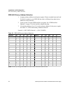
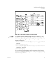
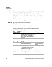
Figure 2.4 User Signals J7 Connector
J7-1 External TTL shutdown input signal
(See “TTL Shutdown”)
J7-2 Polarity signal, open collector
(asserted by VSET -x)
J7-3 Isolation signal, open collector
(asserted by OUT OFF)
J7-4 Fault signal, open collector
(asserted when bit set in fault register)
J7-5 External Vcc, 15V maximum
(supplied by connecting and operating an external source)
J7-6 External ground and shutdown return
(supplied by connecting and operating an external source)
J7-7 Open collector user signal
(asserted by AUXA ON)
J7-8 Open collector user signal
(asserted by AUXB ON)
Note: On some models, the J7 connector is rotated 180 degrees.