


23
9. Do not backfeed the AC output of the in-
verter with incoming AC power. A backfeed
occurs when AC power from shorepower or
generator is connected to the output of the in-
verter. This will damage the inverter and void
the warranty. Remember that
incoming AC
must be fed only to the AC input and never the
AC output. Always check for AC voltage before
connecting wires to the AC output. Do NOT
turn the inverter ON until all AC connections
have been made. Backfeeding the inverter
voids the warranty.
10. Do not connect the AC input to the AC
output. This would be equivalent to plugging
the battery charger into the inverter. This could
occur if the unit’s AC output is connected to the
entire leg of a circuit breaker panel, then a circuit
breaker on that leg is used to feed the battery
charger input. This will cause the unit to oscillate
ON and OFF when the unit is in inverter mode.
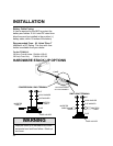
11. Always use proper wire and connectors.
The proper battery cable size is critical. Con-
siderable amperage flows in the DC circuit.
For the FP3000-12, use 3/0 AWG UL Listed
Welding Cable terminated on each with UL
Listed or UL Recognized ring terminal connec-
tors. For the terminal, use Thomas & Betts
(T&B) part number BAL 2038. Be sure the
connectors are attached to the cable using a
method approved by the connector manufac-
turer. For the connections to meet all require-
ments, T&B recommends that each terminal
be crimped in two places with a pressure of 15
INSTALLATION
tons using a hexagonal die. The T&B die has a
code number of 54. After the crimp is made,
the barrel of the terminal and the first inch of
the cable needs to be covered in UL Listed or
UL Recognized heat shrink tubing. Xantrex
recommends a 2-inch length of 3M HDT 0800
tubing. Other heat shrink may be used if it is
UL Listed or UL Recognized as long as the
manufacturer’s directions are followed.
12. If installing in a system which includes an
existing battery charger or AC to DC converter,
make sure these do not operate from the
inverter output AC power. This sets up a
power loop which, due to inefficiencies, will
quickly drain the batteries.
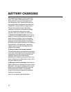
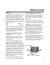
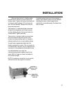
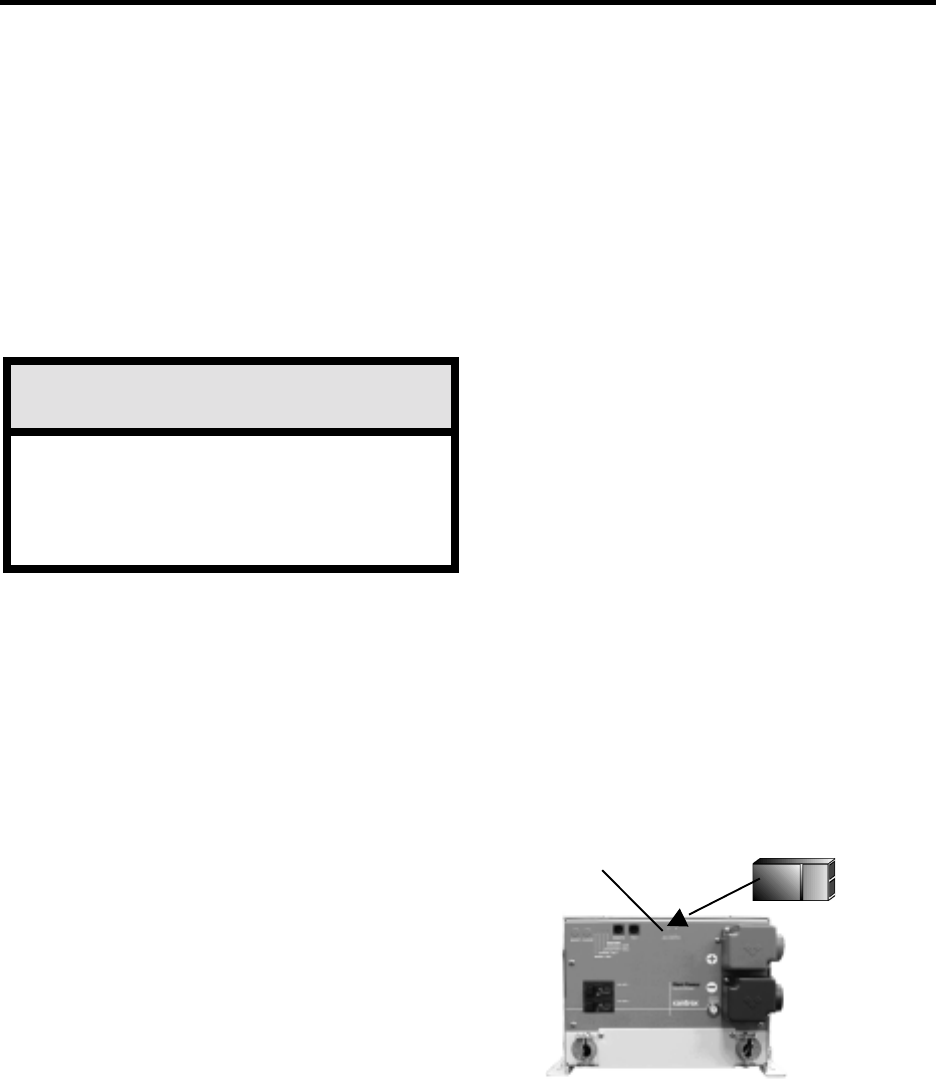
13. An Auxiliary Switch port is located on the
front panel of the unit, covered by a flap. When
installing the unit for operation without a
Remote Control Panel, a jumper must be
installed in the Aux Switch port. The jumper is
shipped in a plastic bag with other installation
parts. DO NOT install the jumper until all cable
connections have been made.
When using a Remote Control Panel, the
jumper is not used.
Do not connect incoming AC from any
source to the AC output of the inverter.
This is known as backfeeding and will
damage the unit and void the warranty.
WARNING
Auxiliary Switch Port
Jumper
Actual size 3/8''L x 3/16''W