


Installation
2–10 975-0059-01-01 Rev A
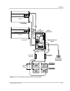
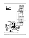
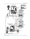
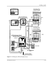
On-Grid AC Wiring for Sine Wave Plus Inverters
Prepare the AC wiring as follows for an on-grid application using series-stacked,
Sine Wave Plus Inverter/chargers. The following steps are illustrated in
Figure 2-5.
Grounding 1. Connect G
ROUND (green) wires:
a) from the primary earth/ground to the main utility panel,
b) from the main utility panel to the AC distribution panel (Sub-panel),
c) from the L1 inverter AC ground bar to the utility panel ground bar,
d) from the L2 inverter AC ground bar to the utility panel ground bar.
Neutral Bonds 2. Connect N
EUTRAL (white) wires:
a) from the Neutral bus in the utility panel to the ground bar in the utility
panel. (Neutral-to-ground bond),
1
b) from the L1 inverter NEUTRAL OUT terminal to the L2 inverter
NEUTRAL 2 terminal (Interter-to-inverter neutral bond),
c) from the L1 inverter N
EUTRAL OUT terminal to the utility or utility panel
neutral bus (Common neutral bond in utility panel),
d) from the L2 inverter N
EUTRAL OUT terminal to the AC distribution panel
neutral bus (Common neutral bond in sub-panel),
Inverter to AC
Distribution Panel
3. Connect H
OT wires:
a) (black) from the L1 inverter AC H
OT OUTPUT (120 Vac) to the inverter
panel L1 terminal.
b) (red) from the L2 inverter AC H
OT OUTPUT (120 Vac) to the inverter
panel L2 terminal.
Inverter to Utility
Panel
4. Connect H
OT wires:
a) (black) from the utility panel HOT L1 terminal to the L1 inverter’s AC1
GRID terminal.
b) (red) from the utility panel HOT L2 terminal to the L2 inverter’s AC1
GRID terminal.
5. Torque all inverter terminal block connections to 25 inch-pounds.
1.This connection may already exist from the original installation of AC service to the
building.