


30 Assembly
MAN0475 (9/21/2005)
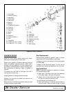
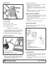
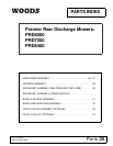
Install Top Link
9. Link, rear offset
10. Link, front offset
11. Link, U-bracket
30. Sleeve, .62 x .84 x 2.88
40. Screw, HHCS 1/2 NC x 4-3/4 GR5
44. Nut, flanged lock 1/2 NC
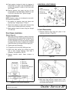
Figure 30. Top Link Assembled
1. Insert cap screw (40) through rear offset links (9),
pipe (30), U-bracket (11) and front offset links (10)
as shown and tighten securely with nut (44).
2. Tighten hardware on rear frame lug and offset link.
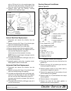
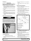
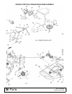
Install Rear Caster Arm
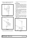
Figure 31. Rear Caster Arm Installed
1. Remove rear caster wheel assembly (20) from
shipping position and install as shown in Figure 31
using the same bolts (60) and nuts (44).
2. Repeat for opposite side.
3. Tighten bolts so that caster arm is snug against
deck bracket, but not fully torqued.
NOTE: Refer to Front Caster Wheel Interference
Check, page 13 for possible front caster arm posi-
tions.
4. Attach front caster arm in desired position and
tighten snug against deck bracket.
Torque Caster Arm Hardware
1. Lift mower off shipping pallet and set on a hard
level surface. This allows clearance in the caster
wheel assemblies to be equalized.
2. Tighten all cap screws and nuts on all four caster
wheel arms.
3. Torque all cap screws and nuts to 85 lbs-ft.
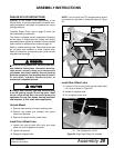
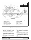
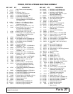
Install Driveline Shield
Attach shield (2), Figure 32, to gearbox (1) with cap
screws (5) and flat washers (4).
Figure 32. Rear Driveshaft Installation
Install Driveshaft
1. Pull locking collar (B) back and, at the same time,
push driveline onto tractor gearbox shaft until
locking device engages.
2. Attach shield anti-rotation chain (C) to drive shield
(2) as shown.
11
10
44
40
9
CM757
30
CM757
20
44
60
20.Caster arm assembly
44.Nut, flanged lock 1/2 NC
60.Screw, HHCS 1/2 NC x 1-3/4 GR5
A. Gearbox input shaft
B. Locking collar
C. Anti-rotation chain
1. Gearbox
2. Shield
3. Driveline
4. Washer, flat standard 5/16
5. Screw, HHCS 8 mm x 1.25P x 16 mm
(Rev. 12/23/2005)