


Dealer Service 25
MAN0475 (9/21/2005)
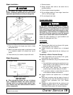
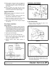
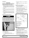
with an OD that will sit on the outside edge of the
seal but will clear the housing. Tubing with an OD
that is too small will bow seal cage and ruin seal.
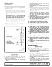
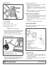
5. Carefully press seal into housing, avoiding
distortion to the metal seal cage.
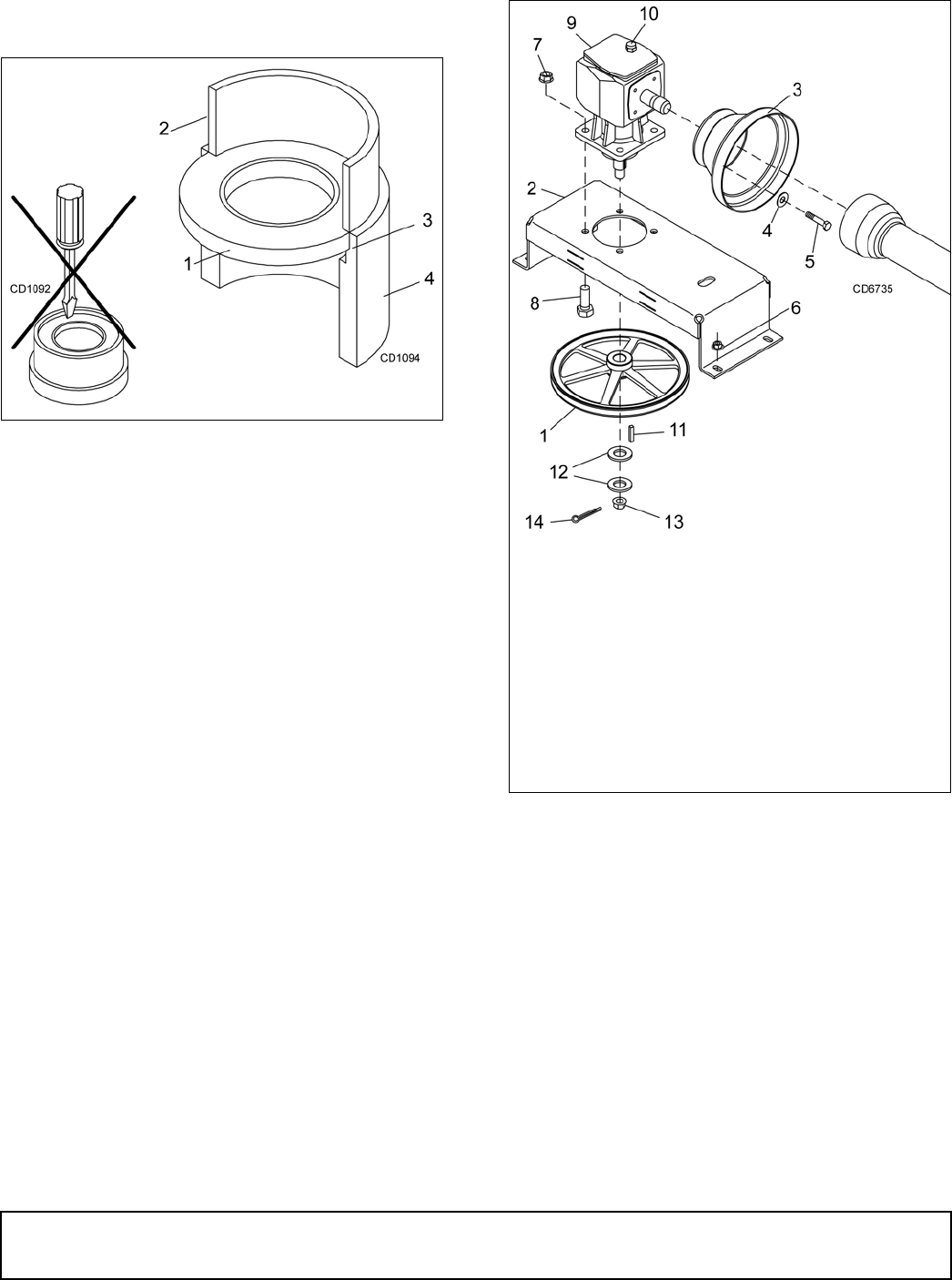
Figure 19. Seal Installation
Vertical Shaft Seal Replacement
1. Disconnect and remove the driveline from the
gearbox.
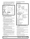
2. Remove vent plug (24). Figure 18, and siphon gear
lube from housing through this opening.
3. Remove gearbox stand from mower deck.
4. Remove gearbox and pulley from gearbox stand.
5. Remove vertical shaft seal (18). Replace with new
seal (see Seal Replacement, page 24).
Vertical seal should be recessed in housing.
NOTE:Distortion to seal cage or damage to seal lip
will cause seal to leak.
6. Fill gearbox with SAE 80W or 90W gear lube until it
runs out the level plug.
7. Assemble gearbox and pulley to gearbox stand.
Attach gearbox stand to mower deck.
Horizontal Shaft Seal Replacement
1. Disconnect and remove the driveline from the
gearbox.
2. Remove vent plug (24), Figure 18, and siphon gear
lube from housing through this opening.
3. If the leak occurred at either end of horizontal shaft,
remove oil cap (20) and/or oil seal (19). Replace
with new one (see Seal Replacement, page 24).
Horizontal seal should be pressed flush with out-
side of housing.
4. Fill gearbox with SAE 80W or 90W gear lube until it
runs out the level plug
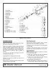
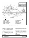
Gearbox Removal from Mower
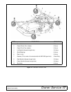
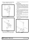
Refer to Figure 20.
Figure 20. Gearbox Stand Assembly
1. Disconnect and remove the rear driveline from the
gearbox (9).
2. Remove vent plug (10) and siphon gear lube from
housing through this opening.
3. Remove gearbox stand (2) from mower deck by
removing four flanged lock nuts (6).
4. Remove four cap screws (5) and washers (4) and
remove shield (3) from gearbox.
5. Remove castle nut (13) and hardware from output
shaft of gearbox.
6. Remove sheave (1) from gearbox.
7. Remove four bolts (8) that attach gearbox to
gearbox stand and remove gearbox.
1. Seal
2. Pipe or tube
3. Seal seat
4. Casting
Pipe or tube
must press at
outer
edge of
Incorrect
Installation
6. Nut, flanged lock 1/2 NC
7. Nut, flanged lock 5/8 NC
8. Screw, HHCS 5/8 NC x 1-3/4
9. Gearbox
10. Vent plug
11. Key, 1/4 x 1/4 x 1-1/4
12. Washer, 25 x 44 x 4 mm
13. Castle nut, M24 x 2
14. Cotter pin, 3/16 x 2
1. Sheave, offset 13.25 PD
2. Gearbox stand
3. Shield
4. Washer, flat 5/16
5. Screw, HHCS 8 mm x
1.25P x 16 mm