


22 Dealer Service
MAN0475 (9/21/2005)
DEALER SERVICE
The information in this section is written for dealer ser-
vice personnel. The repair described here requires
special skills and tools. If your shop is not properly
equipped or your mechanics are not properly trained in
this type of repair, you may be time and money ahead
to replace complete assemblies.
Before working underneath, read manual
instructions, securely block up, and check stability.
Secure blocking prevents equipment from drop-
ping due to hydraulic leak down, hydraulic system
failure, or mechanical component failure.
Keep all persons away from operator control
area while performing adjustments, service, or
maintenance.
Always wear relatively tight and belted clothing
to avoid getting caught in moving parts. Wear
sturdy, rough-soled work shoes and protective
equipment for eyes, hair, hands, hearing, and head;
and respirator or filter mask where appropriate.
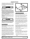
BLOCKING METHOD
See "Blocking Method" instructions on page 16.
BLADE SPINDLE SERVICE
Spindle repair requires special skills and tools. If your
shop is not properly equipped or your mechanics are
not trained in this type of repair, you may be time and
money ahead to use a new spindle assembly.
For reference, the grease fitting is in the top of the spin-
dle shaft.
Permatex
®
3D Aviation Form-A-Gasket or equivalent is
recommended as a sealant.
Spindle Removal
1. Remove blade from spindle.
2. Remove belt from pulleys.
3. Remove jam nut (1) and washer (3) from top of
spindle shaft, Figure 16.
4. Disassemble split taper bushing (5) (located on top
of pulley) by removing the two bolts (2) and
washers (4).
5. Insert bolts (2) into the threaded holes of bushing
flange.
6. Tighten bolts alternately to remove split taper
bushing.
7. Remove pulley (6).
8. Remove bolts (19) that attach spindle to mower
frame and remove spindle.
9. Remove grease fitting (21) from top of shaft.
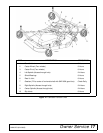
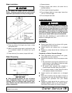
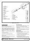
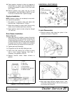
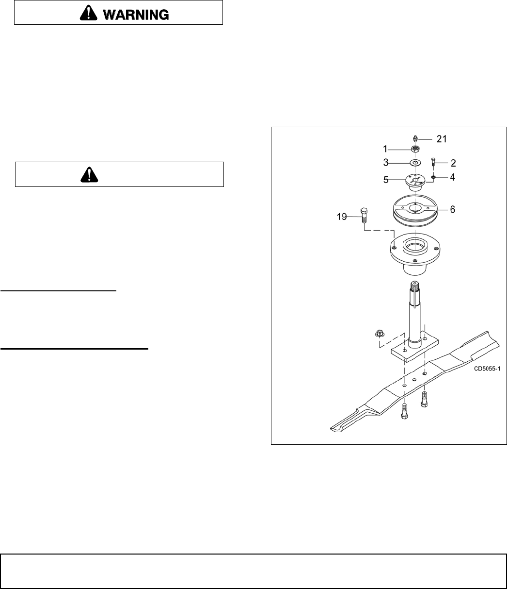
Figure 16. Sheave and Blade Assembly
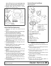
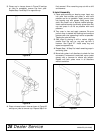
Spindle Disassembly
1. Place spindle assembly in press and press shaft
down through housing.
2. Remove seals from housing.
CAUTION
1. 7/8 NF Jam nut
2. 1/4 NC x 1 HHCS GR5
3. .929 x 1.66 Lock washer
4. 1/4 Lock washer
5. Bushing, H 1 straight
bore w/key
6. Sheave, H 1 BK
19. 1/2 NF x 1-1/4
HHCS GR5
21. Grease fitting