Installation 7
MAN0472 (9/23/2005)
Attach 3-Point Mount to Backhoe
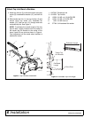
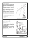
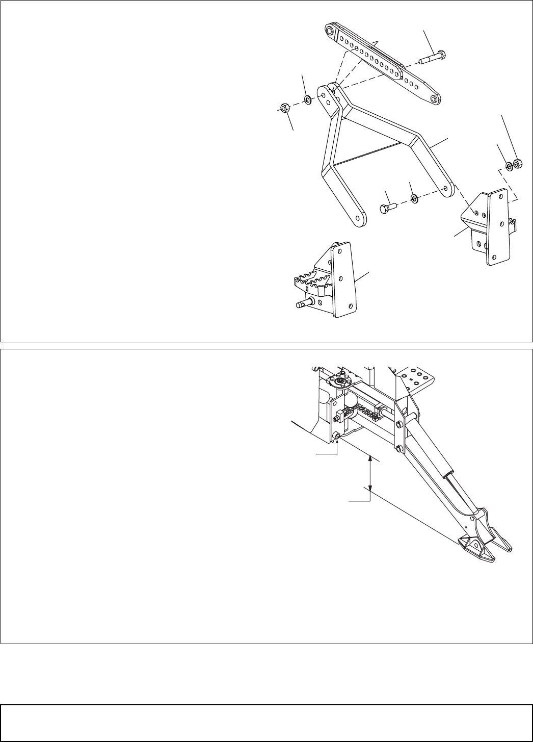
3. Attach lock bar (7) to right (4) and left (5) rear
brackets using cap screws (9), four (two per side)
hardened flat washers (15), and hex nuts (11). Do
not tighten nuts at this time.
4. Swing lock bar up and attach it to the double top
link bar using cap screw (8), hardened flat washer
(15), and hex nut (11). See Figure 5.
4. 1012534 Right rear bracket
5. 1012535 Left rear bracket
7. 1012582 Lock bar
8. 12558 3/4 NC x 4-1/2 HHCS GR5
9. 13759 3/4 NC x 2-1/4 HHCS GR5
10. 14334 3/4 NC x 3 HHCS GR5
11. 1450 3/4 NC Hex nut
15. 57798 3/4 Hardened flat washer
Figure 5. Lock Bar Installation
Attach Backhoe to Tractor
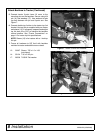
1. Back tractor up to backhoe and 3-point mount.
Center between the tractor rear tires. Position
tractor so that the hydraulic system can be con-
nected. Shut off tractor, set brake, and remove
key.
2. Attach hydraulic pump to tractor PTO or connect
hydraulic hoses.
3. With transmission in neutral, start tractor engine
at idle speed and engage PTO or start hydraulic
flow.
NOTE: Use the backhoe hydraulics to maneuver
the 3-point mount into position. Use care in this
procedure to avoid being trapped between tractor
and backhoe or between backhoe parts.
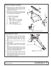
4. Raise backhoe with stabilizer controls and level
backhoe from side to side and front to back. Set
ground clearance between 15-1/2 to 17-1/2
inches. Measure from the center of boom pivot
pin to the ground. See Figure 6.
Figure 6. Ground Clearance
8
7
11
15
3
9
15
4
15
11
CD6779-4
15-1/2" - 17-1/2"
CD4668
Boom
Piviot Pin


