


Installation 11
MAN0472 (9/23/2005)
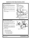
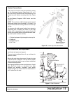
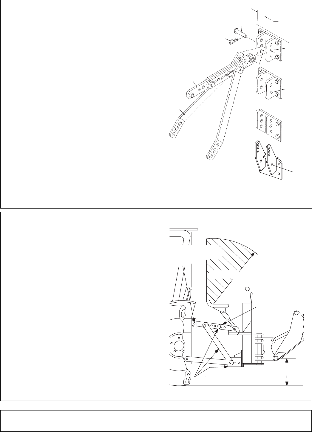
Tractor Connections
There may be more than one hole provided in tractor
top link attachment bracket. Select hole A, B, or C
that most evenly distributes the load between top link
bracket top and bottom mounting bolts. See Figure
10.
For the Massey Ferguson 1455V tractor use hole
position D.
NOTE: The maximum width between tractor top link
attachment plates must not exceed 2-1/2 inches. This
will prevent excessive bending loads to the tractor top
link pin.
For tractors with draft control, select hole closest to
supporting point of floating link. Block or lock draft
control so it is inoperative. Lower manual 3-point lift
control to the lowest position to deactivate draft sens-
ing control (refer to tractor manual).
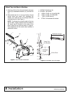
1. Original equipment high-strength tractor top link
2. Safety pin
3. Backhoe top link
4. Saf-T-Lok
Figure 10. Tractor Top LInk Connections
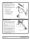
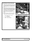
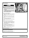
Seat Installation and Adjustment
Install seat and upper seat support.
The seat may be adjusted fore, aft, up, and down for
operator comfort.
Moving the seat down also moves it forward; moving
it up also moves it rearward. The fore and aft adjust-
ment may be used with the up and down adjustment
to obtain desired position.
Never operate backhoe unless manufacturer's 3-point
hitch Saf-T-Lok limiter or sub-frame has been
installed and adjusted. Operator's area (shown
shaded in Figure 11) must be free from obstructions in
a 40" radius from the seat.
Figure 11. Seat Clearance
3
4
A
B
C
2-1/2"
Max.
1
2
D
Massey Ferguson
1455V Top Link
3-Pt Saf-T-Lok
®
Hitch Kit
15-1/2" - 17-1/2"
TRACTOR HIGH
STRENGTH TOP
LINK PIN
40" Minimum Radius
HEAVY-DUTY
TOP LINK