


8 Assembly
MAN0115 (Rev. 3/31/2006)
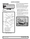
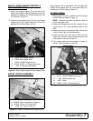
SECURE HOPPER
1. Rotate hopper onto right and left hopper supports.
2. Insert 3/8 lynch pins (18) to attach front hopper
crossmember to support brace as shown in Figure
14.
Figure 14. Latch Locked into Position
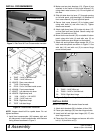
POSITION HOOD FOR SERVICING ENGINE
To flip hood up for servicing engine, follow these steps:
1. Disconnect vacuum hose from hose adapter chute
on vacuum.
2. Remove lynch pins from hopper support (Figure
14).
3. Tilt hopper assembly back.
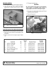
NOTICE
■ Do not attempt to tilt hopper to service position
unless hopper is completely empty. Failure to
empty hopper could result in damage to hopper.
4. On power unit, unhook rubber latches and lift hood
assembly to service position.
5. Secure with prop rod.
Figure 15. Servicing Engine
18
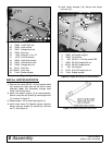
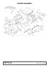
18. 33000 3/8 x 2-1/4 Lynch pins
DP5
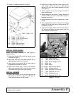
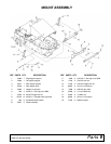
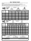
TORQUE SPECIFICATIONS
Ref Cap Screw Qty
Wrench
Size Required Torque
Hardware
Location
4 1/4 NC x 1/2 Whiz bolt 68 7/16 10 lbs-ft (13 N-m) Hopper Assembly
6 3/8 NC x 1-3/4 HHCS 4 9/16 35 lbs-ft (47 N-m) Mount Assembly
8 3/8 NC x 1 FHCS 12 9/16 35 lbs-ft (47 N-m) Mount Assembly
10 1/4 NC x 3/4 Whiz bolt 14 7/16 10 lbs-ft (13 N-m) Hopper Assembly
14 5/16 x 3/4 Sheet metal screw 4 1/2 19 lbs-ft (26 N-m) Hopper Assembly
19 1/4 NC x 1-1/4 HHCS 1 7/16 10 lbs-ft (13 N-m) Hopper Assembly
31 3/8 NC x 3/4 HHCS 2 9/16 35 lbs-ft (47 N-m) Hopper Assembly