


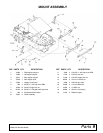


Assembly 7
MAN0115 (Rev. 3/31/2006)
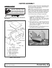
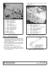
INSTALL REAR HOPPER SUPPORT &
REAR HOPPER PIVOT
1. Attach rear hopper support (3) to the rear of the
power unit using four flanged head cap screws (8),
standard flat washers (9), and two flange lock nuts
(7) as shown in Figure 11.
2. Attach the rear hopper pivot (4) to the rear hopper
support using four flanged head cap screws (8),
washers (9), and flange lock nuts (7).
Figure 11. Rear Hopper Support & Rear Hopper Pivot
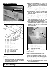
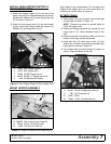
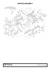
MOUNT HOPPER ASSEMBLY
Figure 12. Hinge Pin Installed (Left Hinge Shown)
Align hinges of rear crossmember (12) on hopper with
hinges of rear hopper pivot (4). Insert clevis pins (14)
and hair pins (15) as shown in Figure 12.
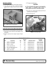
ATTACH CABLE
1. Attach cable (10) to rear of power unit on both right
and left sides as shown in Figure 13.
NOTE: Remove cap screw for ground cable on
21D & 25L power units.
2. Secure with flanged cap screw (8), washer (9), and
flange lock nut (7). Leave hardware loose at this
time.
3. Remove the fourth whiz bolt and whiz nut from the
bottom of both right and left side panels.
4. Install whiz bolt (16), other end of cable (10), flat
washer (9), and whiz nut previously removed in this
hole position as shown in Figure 13.
5. Pivot hopper back and allow weight of hopper on
cables. Torque hardware at this time.
Figure 13. Cable Installed (Right Side Shown)
8
8
7
8
9
7
4
3
DP4
7
9
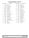
3. 74082 Rear hopper support
4. 73678 Rear hopper pivot
7. 15030 3/8 NC Flange lock nut
8. 62153 3/8 NC x 1 Flanged cap screw
9. 565 3/8 Standard flat washer
14
15
12
4
DP2
4. 73678 Rear hopper pivot
12. 1000679 Rear cross channel (Hopper)
14. 63523 3/4 x 4-1/2 Clevis pin (2)
15. 2688 5/32 Hair pin cotter (2)
DP3
16
7
8
9
9
10
7. 15030 3/8 NC Flange lock nut (2)
8. 62153 3/8 NC Flanged cap screw (2)
9. 565 3/8 Flat washer (4)
10. 73957 Cable
16. 70068 1/4 NC x 3/4 Whiz bolt (2)
(Rev. 8/17/2007)