


Assembly 5
MAN0115 (Rev. 3/31/2006)
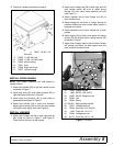
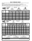
5. Torque all hardware according to page 8.
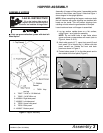
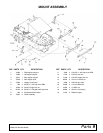
Figure 6. Door Assembly
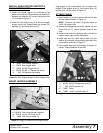
INSTALL DOOR HANDLE
NOTE: Turn hopper assembly over and support in
upright position.
1. Attach door handle (29) to left door handle mount
as shown in Figure 7.
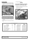
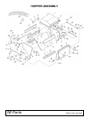
2. Install stop lever (49) and rubber bumper (50) to
right side panel as shown in Figure 8.
3. Install latch pivot bracket (42) to both sides of
grasscatcher as shown in Figure 8.
4. Attach door latches (44) to latch pivot brackets.
Adjust latch brackets (28) so that the door latches
will hold the door tightly shut (see Figure 8).
INSTALL LINKAGE
1. Attach door linkage rod (36) to both right and left
door hinge as shown in Figure 7 and Figure 8.
Place head of clevis pin to the outside.
2. Attach latch linkage rod (36) to both right and left
door handle mount. Be sure to install spring
bracket (35) into clevis when attaching left side
(see Figure 7).
3. Attach opposite end of door linkage rod (45) to
door handle mount.
4. Adjust linkage so that there is a slight amount of
pressure holding the door closed when handle is
snapped over center.
5. Attach opposite end of latch linkage rod to door
latches.
6. Attach spring (34) to hole in side panel with spring
anchor (35) on left side and to spring bracket (33)
as shown in Figure 7.
7. Adjust latch linkage rods so that the door latches
will release just before the door opens when the
door handle is moved forward.
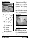
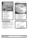
Figure 7. Left Side
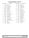
4. 70067 1/4 NC x 1/2
Whiz bolt
5. 70065 1/4 NC Whiz nut
10. 70068 1/4 NC x 3/4 Whiz bolt
23. 70026 Nylon bearing
24. 70531 Door
26. 70536 Right door hinge
27. 70537 Left door hinge
34
32
31
39
35
33
48
29
36
39
40
40
40
45
29. 70526 Hopper handle
31. 1686 3/8 NC x 3/4 HHCS
32. 15030 3/8 NC Flange lock nut
33. 70546 Link
34. 70834 Spring
35. 1001501 Spring anchor bracket
36. 70547 Linkage latch rod
39. 70024 Clevis pin, 5/16 x 25/32
40. 1326 Cotter pin, 1/8 x 1/2
45. 70548 Linkage door rod
48. 64151 Clevis pin, 3/8 x 1-1/8