Assembly 41
MAN0390 (Rev. 4/6/2007)
INSTALL TONGUE DS96 & DS120
CUTTERS
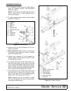
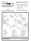
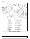
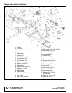
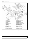
Refer to Figure 36.
1. Place tongue (1) between inner mast plates.
NOTE: DS96 only has one set of mast plates. Fig-
ure 36 shows the DS120 cutter frame.
2. Place washer (46) and sleeve (16) on cap screw
(44).
3. Place washer (47) between mast plates and
tongue, insert cap screw (44) with washer (46) and
sleeve (16) through mast plate and tongue. NOTE:
Washers (47) are only required on DS120 cutters.
4. Secure with second washer (46) and lock nut (45).
5. Attach front half of attitude rod to lug on tongue
using clevis pin (17) and cotter pin (48).
6. Raise front of cutter and install parking jack (6) to
support tongue.
7. Attach safety tow chain (5) to tongue using cap
screw (44), washer (47), and lock nut (45). Be sure
chain links do not interfere with tractor drawbar.
INSTALL 3-JOINT DRIVELINE
Install Driveline
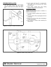
Refer to Figure 36.
1. Coat input shaft of gearbox shaft with light coating
of grease.
2. Attach slip clutch on driveline (9) to input shaft of
gearbox. Tighten cap screws (33) and lock nut
(34).
3. Attach rear tether chain on driveline to clip on
plastic gearbox shield.
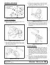
Install H-Frame
1. Place H-frame (2) over front of tongue and align
holes.
2. Secure H-frame to tongue using cap screw (42),
two sleeve (3), two cup washers (4) and lock nut
(43).
Attach Driveline to H-frame
NOTE: Select holes in H-frame that will allow driveline
to run level. Refer to Operation section for driveline
height. Final adjustment will be necessary when cutter
is attached to the tractor.
Place driveline bearing carrier between H-frame (2)
and secure with clevis pin (7) and cotter pin (49).
Install Front Drive
1. Slide rear yoke of front driveline (8) over shaft of
driveline (9) and align with notch on shaft.
2. Secure drives together using cap screw (39) and
lock nut (38).
3. Attach tether chain on front half of driveline (8) to
H-frame (2).
Install Drive Shield & Hose Holder
1. Attach drive shield (13) to driveline carrier bearing
using two cap screws (35) and lock washers (36).
2. Attach hydraulic hose holder (15) to the top hole in
H-frame (2) with cap screw (41), sleeve (14), and
lock nut (40).
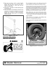
Install SMV Bracket
1. Attach SMV bracket (19) to the top of center
gearbox using two cap screws (32).
2. Attach SMV emblem (20) to SMV bracket using
two round head cap screws (30) and hex nuts (31).


