


Hydraulic Installation 9
MAN0530 (6/30/2006)
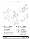
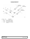
1014620 HOSE KIT INSTALLATION
Keep hands and body away from pressurized
lines. Use paper or cardboard, not hands or other
body parts to check for leaks. Wear safety goggles.
Hydraulic fluid under pressure can easily penetrate
skin and will cause serious injury or death.
Make sure that all operating and service person-
nel know that if hydraulic fluid penetrates skin, it
must be surgically removed as soon as possible by
a doctor familiar with this form of injury or gan-
grene, serious injury, or death will result. CON-
TACT A PHYSICIAN IMMEDIATELY IF FLUID
ENTERS SKIN OR EYES. DO NOT DELAY.
Air in hydraulic systems can cause erratic oper-
ation and allows loads or equipment components
to drop unexpectedly. When connecting equipment
or hoses or performing any hydraulic maintenance,
purge any air in hydraulic system by operating all
hydraulic functions several times. Do this before
putting into service or allowing anyone to
approach the equipment.
Protective hose sleeves must cover all hydrau-
lic hoses within 20 inches of the operator and be
secured onto metal hose fittings. Replace hoses or
sleeves if damaged or if protective sleeve cannot
be properly positioned or secured.
Make sure all hydraulic hoses, fittings, and
valves are in good condition and not leaking before
starting power unit or using equipment. Check and
route hoses carefully to prevent damage. Hoses
must not be twisted, bent sharply, kinked, frayed,
pinched, or come into contact with any moving
parts. Operate moveable components through full
operational range to check clearances. Replace
any damaged hoses immediately.
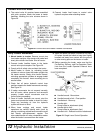
IMPORTANT
■ If hydraulic lines are not connected as shown in
this manual, the control valve may be damaged. A
blocked outlet (RETURN) or improper hose
connection will cause pressurized oil to enter the
return circuit and damage the valve.
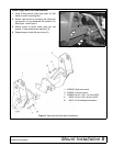
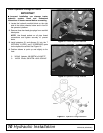
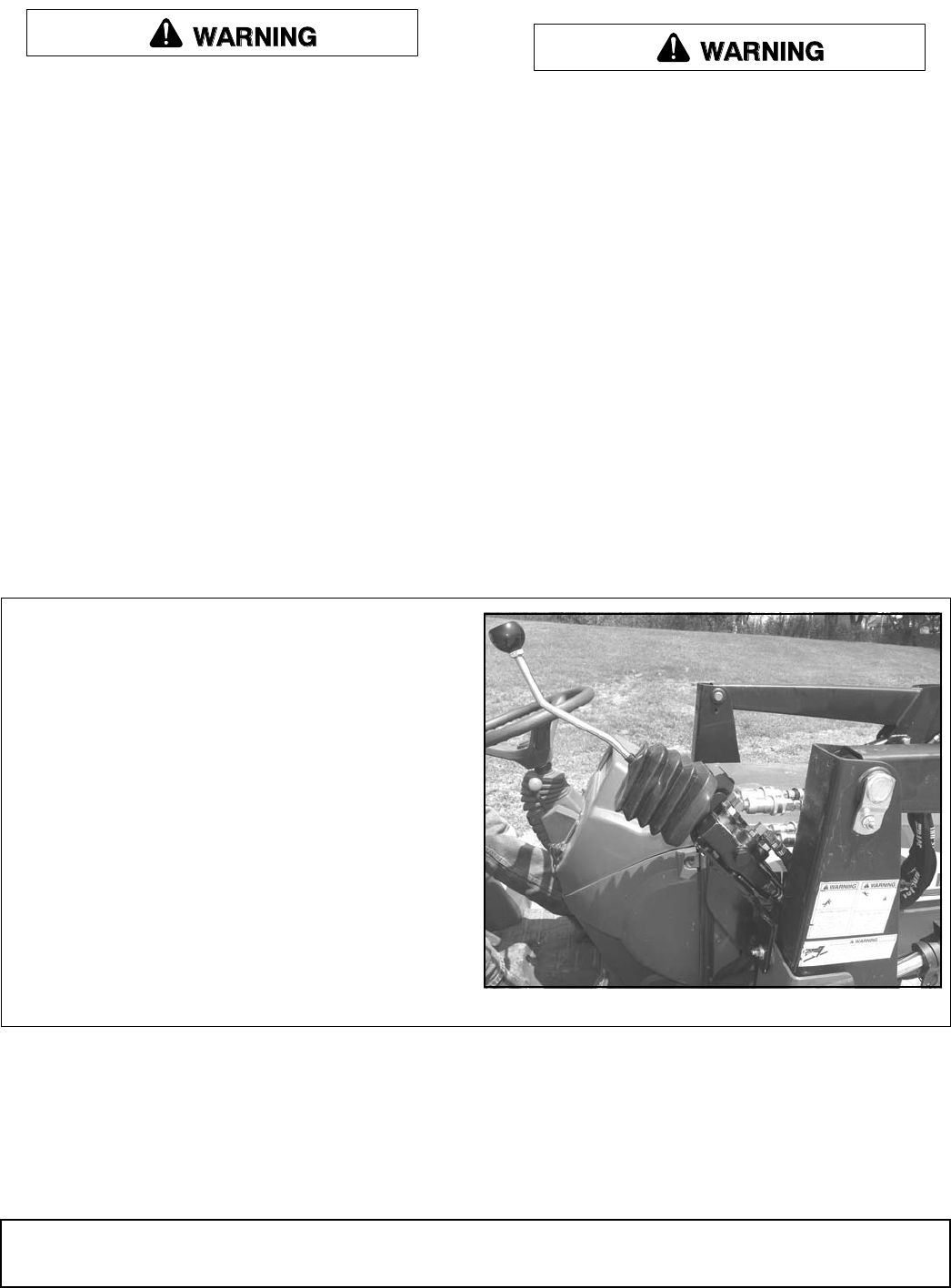
General Description
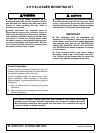
Completion of this hose kit installation requires con-
nection to a Woods single-lever control valve,
mounted to the right loader mount with a mounting
bracket as shown in Figure 14.
Mount control valve to loader mount before proceed-
ing.
Figure 14. Single-Lever Control Valve
DP8