


12 Hydraulic Installation
MAN0530 (6/30/2006)
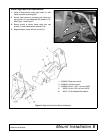
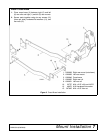
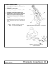
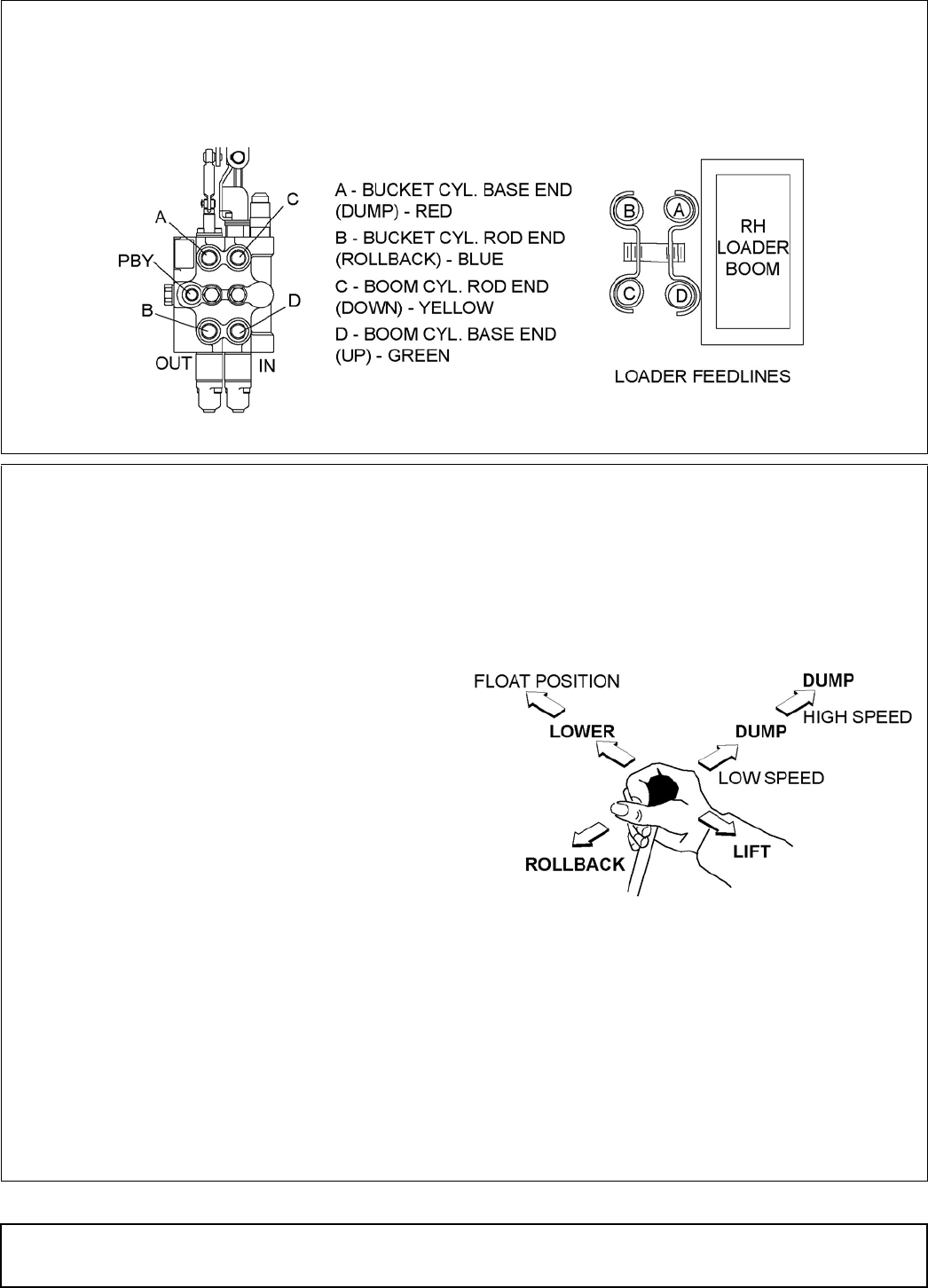
Connect Work Port Hoses
1. The control valve kit contains hoses assembled
with quick couplers. Attach the hoses to loader
feedlines, following the color scheme shown in
Figure 20.
2. Connect loader feed hoses to control valve
hydraulic couplers when attaching loader.
Figure 20. Control Valve and Loader Feedline Connections
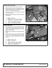
Verify Control Movements
1. Mount loader to tractor: Remove mount pins
from loader uprights. Align tractor with loader and
slowly drive tractor into loader. Shut off tractor.
2. Connect loader feedline hoses to the loader
control valve quick couplers. See Figure 20.
3. Comply with all safety rules and start the tractor.
4. Mount loader to tractor by activating bucket
cylinders to raise or lower the loader uprights into
the loader mounts. Slowly drive tractor forward,
activating appropriate cylinders to engage loader
completely into mounts. Insert mounting pins to
secure loader.
5. Check that all tractor hydraulic control lever
positions operate the loader movements correctly.
See Figure 21.
6. If loader movements do not respond correctly,
shut off tractor, relieve pressure, and reconnect
properly. Loader control movements must be
correct before proceeding.
7. Once all loader functions are correct, start the
tractor and operate the loader to check for leaks.
Purge any remaining air from the hydraulic
system and check oil level.
8. When hose routings and correct loader
operations are verified, identify each circuit by
placing a matching colored band around the male
and female quick-disconnect coupler. The
color-coded bands will make reinstallation easier
when the loader is removed from the tractor.
9. Attach the plastic tie straps (included in kit) every
20 inches around the hoses to keep them tightly
bundled and away from contact with the ground
or other moving parts on the tractor or loader.
10. Before operating the loader, make sure that the
Pre-Delivery, Delivery, and Pre-Operation Check
Lists from the Loader Operator’s Manual have
been completed.
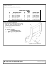
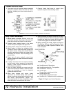
Figure 21. Single Lever Control Operation
● Handle forward - Boom down
● Handle forward to limit - Float position
● Handle back - Boom up
● Handle right -
Dump bucket or attachment (slow)
● Handle right to limit -
Dump bucket or attachment (fast)
● Handle to left - Rollback bucket or attachment