


-- 5 --
ASSEMBLY
WARNING: Stop engine and be sure
the impeller blades have stopped turning be-
fore opening the vacuum inlet door or at-
tempting to insert or remove the vacuum or
blower tubes. The rotating blades c an cause
serious injury. Always disconnect the spark
plug before performing maintenance or ac-
cessing movable parts.
WARNING: If you receive your unit
assembled, check each step to insure your
unit is properly assembled and all f asteners
are s ecure. Follow all safety information in
the manual and on the unit .
D A standard screwdriver is required for as-
sembly.
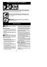
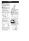
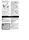
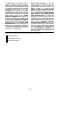
BLOWER TUBE ASSEMBLY
1. Align the rib on the blower tube with the
groove in t he blower outlet; slide the tube
into place.
NOTE: K nobmustbe looseenough toallow
blower tube to be inserted in blower outlet.
Loosen knob by turning counterclockwise.
Blower
Tube
Blower
Outlet
Rib
Groove
2. Securethetubeby turningthe knob clock-
wise.
3. Toremove th etube,turn theknobcounter-
clockwise to loosen the tube; remove the
tube.
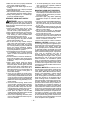
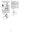
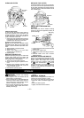
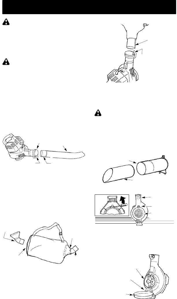
VACUUM BAG ASSEMBLY
1. Open the zipper on the vacuum bag a nd
insert the elbow tube.
2. Push the small end of the elbow tube
through t he small opening in the bag.
Small
Opening
Zipper
Opening
Elbow
Tube
Rib
NOTE: Make sureedgeofthesmallopening
is flush against the flared area of the elbow
tube, and the rib on the elbow tube is on the
bottom.
3. Closethezipperonthebag.Makesurethe
zipper is closed completely .
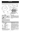
4. Remove blower tube from engine.
Rib
Groove
5. Inserttheelbowtubeintothebloweroutlet.
Make sure elbow tube rib is aligned with
the blower outlet groove.
6. Turnknobclockwisetosecureelbowtube.
VACUUM TUBE ASSEMBLY
WARNING: Stop engine and be sure
the impeller blades have stopped turning be-
fore opening the vacuum inlet door or at-
tempting to insert or rem ove the vacuum or
blower tubes. The rotating blades can cause
serious injur y.
1. Align the lo wer vacuum tube as shown.
Push lower vacuum tube into upper vacu-
um tube.
Lower Vacuum Tube
Upper Vacuum
Tube
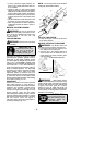
2. Insert thetip ofascrewdriverinto thelatch
area of the vacuum inlet.
Latch Area
Blower
Outlet
Vacuum
Inlet Cover
Latch
Area
3. Gentlytilt thehandle ofthe screwdriverto-
ward the back of the unit to r elease t he
latch while pulling up on the vacuum inlet
cover w ith your other hand.
4. Hold the vacuum inlet cover openuntilup-
per v acuum tube is installed.
Vacuum Inlet
Vacuum
Inlet
Cover
Retaining P ost