


5
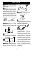
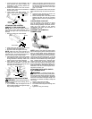
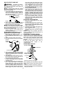
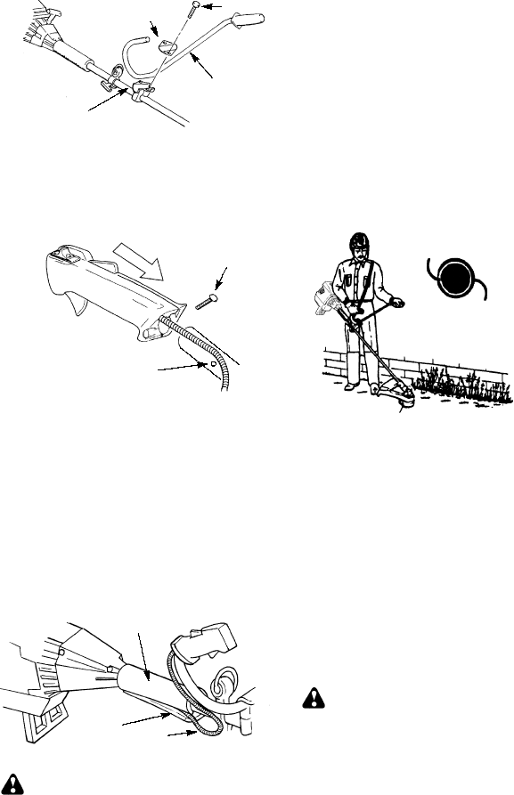
1. Locate the decal on the handlebar. T his
decal includes two arrows. Position the
handlebar on the mounting bracket be-
tween these arrows.
2. Position the bracket cover over the han-
dlebar. Again make sure the handlebar is
between the arrows.
3. Insert screws and hand tighten only.
These screws will be tightened later.
Bracket Cover
Screw
Mounting
Bracket
Handlebar
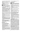
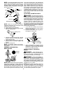
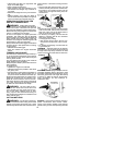
ATTACHING THE CONTROL
HANDLE TO THE HANDLEBAR
NOTE:
Make sure the wire going to the con-
trol handle is routed below the tube and re-
mains on the right side of the handlebar and
the tube.
1. Remove screw from control handle.
Screw Hole
Screw
2. Slide handle onto the right sideof thehan-
dlebar and align the screw hole.
3. Re-insert screw and tighten securely.
NOTE:
Make sure the c ontrol handle is on
the right side of the unit as shown in the il-
lustration below, and the ON/OFF switch islo-
cated on the top of the control handle.
4. Adjust thehandlebar tothe properposition
and tighten the two screws you left l oose
during handlebar assembly. Make sure
these screws are securely tightened.
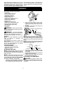
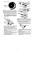
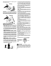
5. After attaching the control handle and
tightening the handlebar, route the wire
from the control handle through the slit in
the bottom of the foam grip.
Slit
Wire
Foam Grip
ASSEMBLY OF SHOULDER STRAP
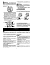
WARNING:
Propershoulderstrapand
handlebar adj ustments before s tar ting the en-
gine are required.
1. Tr y on shoulder strap and adjust for fit and
balance before starting the engine or begin-
ning a cutting operation.
2. Insert your right arm and head through the
shoulder strap and allow it to rest on your
left shoulder. Makesure thedanger sign is
on your back and the hook is to the right
side of your waist.
NOTE:
Aone-half twist isbuilt in theshoulder
strap toallow thestrap torest flat ontheshoul-
der.
3. Adjust the strap, allowing the hook to be
about 6 inches below the waist.
4. Fasten the strap hook to the clamp l ocated
between the foam grip and the mounting
block and lift the tool to t he operating posi-
tion.
CONFIGURING YOUR UNIT
You can configure your unit using a cutting
head for grass and light weeds, or a brush
blade for cutting saplings and similar size ma-
terial. Go to the section for the desired
configuration and follow the instructions for
assembling your unit.
ASSEMBLY INFORMATION --
TRIMMER HEAD
TRIMMER
HEAD
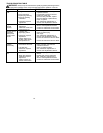
NOTE:
Remove the blade and metal shield
before attaching the plastic shield andtrimmer
head. To remove blade, push in locking l ever
and hold. Rotate blade nut until the locking le-
verfalls intooneofthegrooves inthe dustcup.
Continue to hold the locking lever. This will
keepthe shaftfromturning while loosening the
blade nut. Removeblade nutby turning clock-
wise. Release locking lever. Remove both
washers and blade. To remove metal shield,
loosen and remove the four mounting screws.
See ATTACHING THE METAL SHIELD and
INSTALLATION OF THE METAL BLADE for
illustrations. Be sure to store all parts and in-
structions for future use.
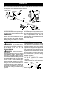
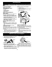
ATTACHING THE PLASTIC SHIELD
AND TRIMMER HEAD
WARNING:
The shield must be prop-
erly installed. The shield provides partial protec-
tion from the r isk of thrown objects to the opera-
tor and others and is equipped with a line limiter
which cuts excessline to the proper length. The
line limiter (on underside of shi eld) is sharp and
can cut you.
1. Remove wing nut from shield.
2. Insert bracket into slot on s hield.
3. Pivot shield until bolt passes through hole
in bracket.
4. Tighten the wing nut securely.