


4
locale where such regulations exist, you are
legally responsible for maintaining the operat-
ing condition of these parts. Failure todo sois
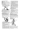
a violation of the law. For normal homeowner
use, the muffler and spark arresting screen
will not require any service. After 50 hours of
use, we recommend that your muffler be ser-
viced or replaced by your authorized s ervice
dealer.
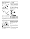
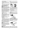
ASSEMBLY
CARTON CONTENTS
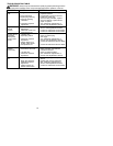
Check carton contents for the f ollowing:
S
Brushcutter
S
Tube mounting screws (2)
S
Tube mounting nuts (2)
S
Handlebar screws (2)
S
Blade shield screws (4)
S
Cupped washer (1)
S
Large nut for installing blade (1)
S
Long hex key wrench (1)
S
Short hex key wrench (1)
S
Bracket cover
S
Shield for use with blades
S
Shield for use with trimmer head
S
Semi-automatic trimmer head
S
Shoulder strap with warning
S
Brush blade
S
Handlebar
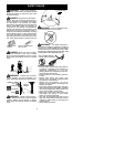
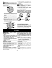
WARNING:
Always stopunit anddis-
connect spark plug before performing anyas-
sembly procedures.
WARNING:
If received assembled,
repeat all steps to ensure your unit is properly
assembled and all fasteners are secure.
Examine parts for damage. Do not use dam-
aged part s.
NOTE:
If you need assistance or find that
parts are missing or dam aged, call
1-800-554-6723.
It is normal for the fuel filter to rattle in the
empty fuel tank.
Finding fuel or oil residue on muffler is normal
due to carburetor adjustments and testing
done by the m anufacturer.
TOOLS REQUIRED
S
2 hex key wrenches (provided)
S
Adjustable wrench or large pliers
S
Phillips screwdriver
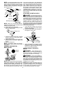
ATTACHING THE TUBE
NOTE:
Illustr a tion sw ith inthissection will help
in identifying the assembly steps. Be sure to
rea d eac h se c tio n and r e v ie w the illustra tio n s ,
before you begin.
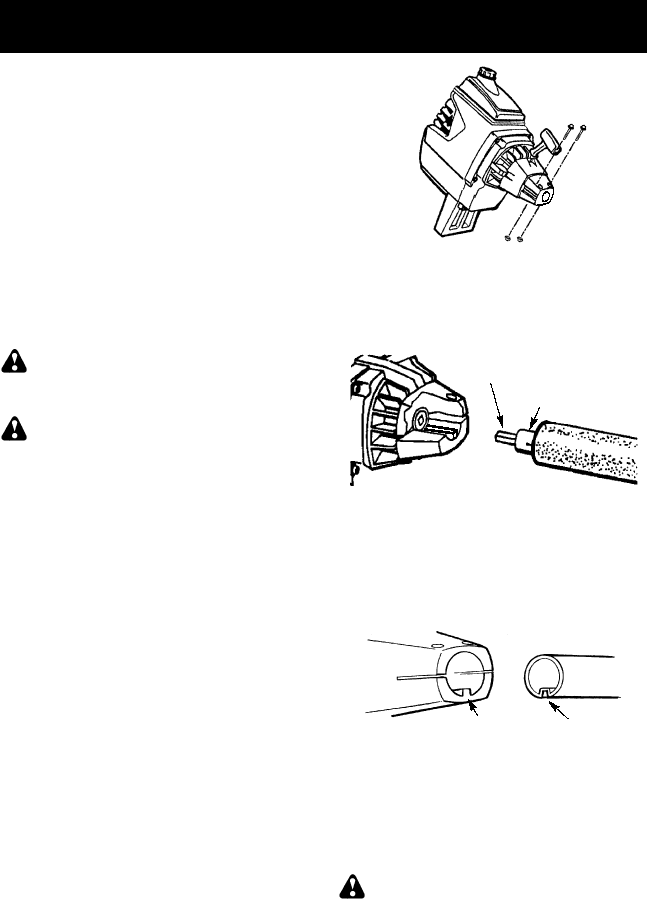
NOTE:
A drive shaft is located in the center
of the tube. Make s ure this shaft does not fall
out ofthe tube. Dirton theshaft will significant-
ly reduce the life of the unit. If t his shaft falls
out, clean, relubricate, and re-install.
1. Insert the 2 tube assembly screws and
nuts asillustrated. Keep loose at thist ime.
You will tighten them duri ng a later s tep.
2. Some units may include a plastic cover
over the end of the tube. If your unit in-
cludes any covering, remove the cover at
this time.
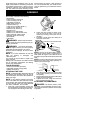
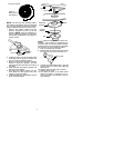
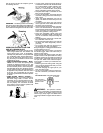
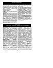
3. Pull about 1/2 inch of the drive shaft out of
the inside of the tube.
Pull about 1/2 inch from tube
Tube
NOTE:
The end of the drive shaft i s s quar e.
This square end fits inside a squar e hole in a
shaft inside the engine. Look inside the end of
theengineandyouwillseethesquar eholeinthe
sha ft.
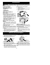
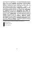
NOTE:
The end of thetube has agroove that
aligns with a ridge in the engine opening. Lo-
cate the groove and ridge.
GrooveRidge
4. Align the groove in the tube with the ridge
in the engine opening. Insert the tube into
the opening.
5. Firmlypushthetubeintoengine untilitwillno
longer go into the opening.
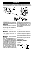
6. Tighten the screws, using one of the hex
keys provided with t he unit.
ATTACHING THE HANDLEBAR
DANGER:
The barrier portion of the
handlebar must be installed as shown to pro-
vide a barrier between operator and the spin-
ning blade.