


Maintenance Instructions ADJUSTMENTS
85
Use the following procedures to check and adjust
clutch disengagement and brake action:
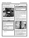
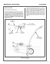
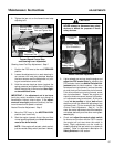
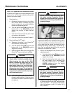
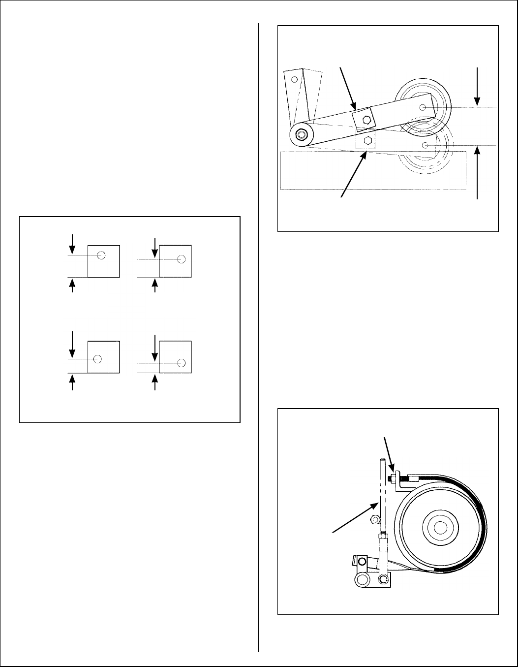
Stop Block Eccentric Adjustment - Step 1
Use the stop block attached to PTO belt tightener
arm to set the bottom position of the clutch idler pul-
ley in the disengaged position. The stop block
should contact the chassis to stop the clutch idler
pulley from moving further down in the disengaged
position. If the stop block is not contacting the
chassis in the disengaged position, it will be neces-
sary to loosen the brake band adjustment nut.
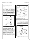
The stop block is an “eccentric” block that will allow
four adjustment positions from 5/16 in. (8 mm) to
11/16 in. (17 mm).
PTO Belt Tightener Stop Block Adjustments
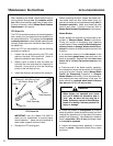
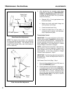
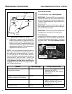
Clutch Idler Pulley Travel Adjustment - Step 2
Adjust the stop block to give 1 in. (25 mm) to 1-1/2
in. (38 mm) pulley travel from “clutch engaged” to
“clutch disengaged”. To check and adjust the pulley
travel, first engage the clutch, then measure the dis-
tance the pulley moves down as the clutch is disen-
gaged and the stop block contacts the frame.
NOTE: The importance of this adjustment is if the
pulley travel is excessive and the belt develops too
much slack, the belt will derail when disengaged.
Clutch Idler Pulley Travel Adjustment
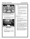
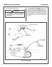
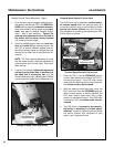
Blade Brake Band Adjustment - Step 3
After the pulley travel is set, make the following ad-
justment as needed:
1. Adjust the blade brake band, using the adjust-
ment nut until there is a gap of approximately
1/8 in. (3 mm) between the PTO belt tightener
stop block and chassis. If there are not enough
threads on the brake band for adjustment,
lengthen the brake actuator rod.
Blade Brake Band Adjustment
11/16 in.
(17 mm)
9/16 in.
(14 mm)
7/16 in.
(11 mm)
5/16 in.
(8 mm)
Engage
Disengage
Pulley
Travel
1 in. to 1-1/2 in.
(25 mm to 38 mm)
Stop Block
Contacting Frame
Stop
Block
Brake Actuator
Rod
Blade Brake Band
Adjustment Nut