


Assembly Instructions
28
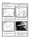
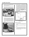
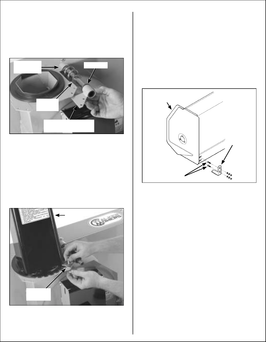
5. Insert the 1-11/16 in. (43 mm) plastic bushing in-
to the bushing support and place this over the
shaft on the rotation worm.
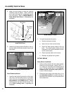
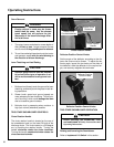
6. Install the rotation worm assembly through the
tube weldment with the attaching plate of the
support on the underside of the chute base lip.
Install Rotation Worm Assembly
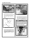
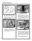
7. Install the chute over the plastic insert and se-
cure with four retaining plates, using two (2) 1/4
x 1/2 in. bolts, lock washers, and nuts in each of
the three (3) standard retaining plates, and two
(2) 1/4 x 3/4 in. bolts, lock washers and nuts in
the rear right retaining plate which also secures
the support. Torque all bolts to 10 ft-lb. (13.6
N·m).
Install Chute over Plastic Insert
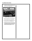
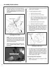
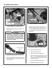
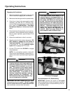
8. Insert two (2) 5/16 x 1 in. carriage bolts through
each of the skid shoes from inside the bend.
Place a flat washer, lock washer, and nut loose-
ly on each bolt and place the bolt heads through
the round holes in the outer ends of the bottom
angle of the snowblower body. Adjust the skid
shoes to allow the required clearance under the
cutting edge. Slide the square shank portion of
the bolt head into the slot and torque to 19 ft-lb
(25.8 N·m). Refer to ADJUSTMENTS of Two-
Stage Snowblower Skid Shoes in Mainte-
nance Instructions.
Install Skid Shoes
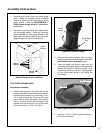
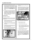
Snowblower Installation
1. Thoroughly clean the drive shaft yoke and install
a 1/4 x 1/4 x 1-1/4 in. key in the reduction shaft
keyway.
2. Slide the drive shaft yoke over the reduction
shaft.
3. Secure the yoke to the reduction shaft with a 1/4
x 2-1/2 in. bolt and nylon locknut. Tighten the
nut and the 3/8 x 3/8 in. allen set screw securely
over the key in the yoke.
Bushing Support
With Attaching Plate
Rotation
Worm
Tube
Weldment
Bushing
Retaining
Plate
Chute
Skid Shoe
Carriage Bolts
Snowblower
Housing