


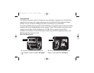
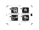
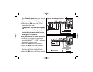
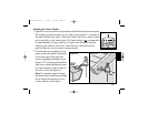
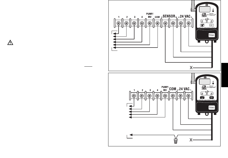
For a Normally-Open sensor type, attach the
Yellow wire to the remaining Sensor terminal.
Tape back the Brown wire. See Figure 3.
4. Attach the two Red wires to the 24 Vac
terminals in either order.
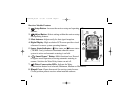
Important: Most controllers equipped
for sensor connection provide a switch to
control the sensor circuit. Check the
switch setting to ensure that it is not in
the Bypass or Off position.
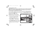
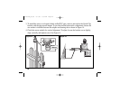
Wiring Procedure II (no Sensor terminals)
1. Locate the valve common wire terminal,
generally labeled “C” or “COM”, and remove
the attached common wire(s).
2. Attach the White wire to this terminal.
3. Splice the Brown wire to the common
wire(s) using a wire nut or electrical tape.
Tape back the Yellow wire. See Figure 4.
4. Attach the Red wires to the 24 Vac terminals.
7
English
TWRFS-I
Figure 3 - Normally-open Sensor
Figure 4 - Splice Valve Common
Red
White
Brown
Yellow
To Valves
To Valves
Common to Valves
and Pump/MV
Red
Red
White
Yellow
Red
Red
White
Brown
Yellow
Red
Red
White
Red
373-0372a_E/S/F 6/7/05 1:59 PM Page 7