


6
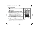
Connecting the Receiver Wires
CAUTION: The receiver requires continuous 24 Vac power for operation. Connecting to
higher power will result in irreparable damage. Ensure that power to the controller has
been removed prior to connecting the receiver wires.
The sensor system is designed to work with most makes and models of irrigation controllers.
• If your controller is equipped for a sensor connection, follow the steps in Wiring Procedure I.
• If your controller is not equipped for a sensor connection, use Wiring Procedure II on page 7.
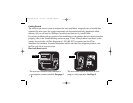
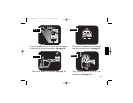
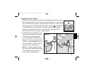
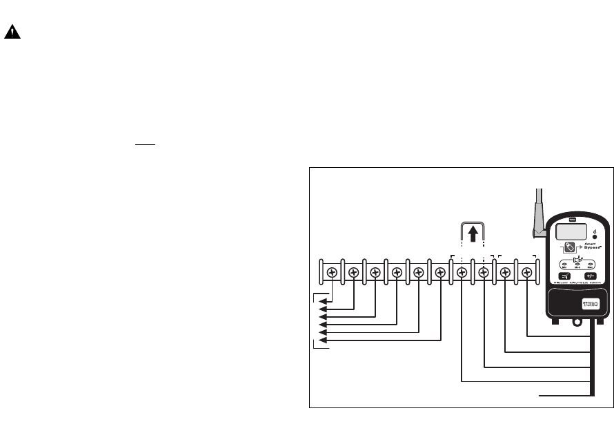
Wiring Procedure I (sensor-ready)
Note: Refer to your controller user’s guide
to determine the type of sensor required:
Normally Closed (NC) or Normally Open (NO).
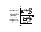
1. Locate the sensor connection terminals,
usually labeled “SENSOR” or “SN.”
Remove the jumper connector (if installed).
2. Attach the White wire to either Sensor
terminal (disregard +/ – polarity if labeled).
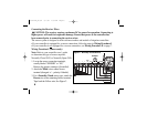
3. For a Normally-Closed sensor type , attach the
Brown wire to the remaining Sensor terminal.
Tape back the Yellow wire. See Figure 2.
COM
PUMP/
MV
24 VAC
21
34
SENSOR
X
TWRFS-I
Jumper
Figure 2 - Normally-closed Sensor
Red
White
Brown
Yellow
To Valves
Red
Red
White
Brown
Red
373-0372a_E/S/F 6/7/05 1:59 PM Page 6