unigreen 21
For instance, having a mistblower with fans and knowing:
- the working length L = 4,0 meters;
- the forward speed of 5,0 km/h;
- the tap lever in position 2;
- the pressure adjusted at 2,0 bars
you will have a flow rate value of 7,0 l/min. and consequently of 210 l/ha.
Similarly, by knowing the l/ha value to be sprayed, as well as the working
speed and distance, we can obtain the lever position and the pressure which
is necessary for treatment.
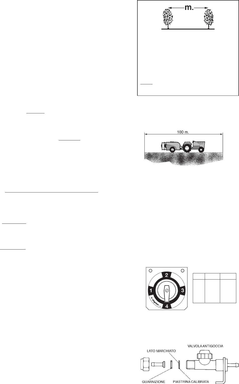
As the speed values indicated in the tables will hardly correspond to the real
ones, at first it will be necessary to calibrate the speed by operating in the
following way. With the equipment in average working conditions (half-filled
tank), with power take-off at 500 r.p.m. and with the fan/s in operation (without
spraying), drive a measured base of 100 meters, possibly on the field on
which you have to work and measure the time (t) in seconds that you need to
drive it.
Then calculate speed according to the formula:
V = S x 3,6 (1)
t
whereas S is the distance in meters (in our case, 100 meters) and t is the
time necessary to drive it.
Example:
if t = 66 seconds, you will have V = 100 x 3,6 = 5,4 km/h
66
It is recommended to repeat the calibration with 2-3 different gears in order to
have more data relating to speed.
As - beyond forward speed - also working width may not correspond to the
ones indicated on the table, by using the flow rate in l/min. of the spraying
head (see last line of table No. 3), you may obtain the volume in l/ha
according to the following formula (2):
VOLUME in l/Ha. = 600 x l/min. (2)
working width (m) x working speed (km/h)
Therefore, if from the initial example only working speed is different from V =
5,4 km/h, you will have:
volume in l/ha = 600 x 7 = 194 l/ha
4 x 5,4
If also working width is different, for instance 3,5 m:
volume in l/ha = 600 x 7 = 222 l/ha
3,5 x 5,4
6.4.1 BATCHING TAPS (SEE PICTURE 20)
On the equipment VENTAGLI (FANS) there are two batching taps which can
be used to quickly change the flow rate to the jets; the long part of the lever
shows the position (f.i. picture 20 = pos. 4). Each tap can carry out four
different positions. In the range of each single mode, for four different
pressures set on the regulator, we obtain four different values of the litre
capacity per minute, for a total of 16 values as you can observe from table
pages 25-26. An increase in pressure means an increase in capacity; a
decrease in pressure means a decrease in capacity. For other types of heads,
the number of positions and the pressure value can be different, as you can
notice on the relevant tables.
6.4.2 CALIBRATED PLATES CP
In the accessories provided with an anti-dripping valve on each sprayer, on
the valve output there is a calibration plate which guarantees an
homogeneous distribution among the various sprayers.
According to the spraying table to be carried out, it is necessary to install the
plate indicated in the table.
NOTE: The plate must be mounted with the side bearing the initials towards
the liquid output (picture 21).
The values indicated on the tables are approximate; according to the mixture
concentration, spraying values can be slightly different. These differences can
be easily corrected by acting on the working pressure. Increasing pressure
means increasing spraying and vice versa.
posiz. Ømm Ø inch
1 Ø1,75 Ø0,07"
2 Ø2,25 Ø0,09"
3 Ø3,50 Ø0,14"
4 Ø4,25 Ø0,17"
4916-47
4916-51
4916-55
4916-70
N.B. to calculate the different ranges it is
sufficient to multiply the value lt/hectare by the
corresponding width indicated in the table and
divide it by the new width.
Example-
In the table: 907lt/ha with row distance 3m.
907x3 = 971 Lt/ha with row distance 2,8m
2,8
FIG. 20
FIG. 21
CALIBRATED PLATE
GASKET
ANTIDRIPPING VALVE
MARKED SIDE


