


18 unigreen
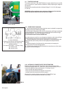
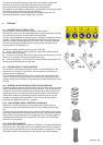
5.5 CLUTCH
Big aluminium and nylon blowers have a centrifugal type clutch that makes it
possible to engage the fan rotor gradually.
This prevents jerky starts, due to the inertia of the fan rotor, which can have a
negative effect on the transmission.
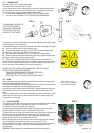
For the centrifugal clutch to work properly the speed of the power-takeoff
mustn’t be less than 450 rpm, especially if you are using the first gear of the
multiplier.
Generally clutches with shoes/plates made of sintered material with a high
coefficient of friction are fitted, on some low power models rubber clutches may
be fitted.
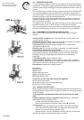
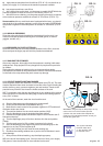
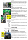
5.6 OPTIONAL DEFLECTORS AND ACCESSORIES
The atomisers are fitted with deflectors underneath for the optimal regulation of
the airflow towards the zone to be treated. To adjust these, simply pull or push
the deflector, positioning it in the desired way (FIG.23).
Top deflectors can also be supplied on request to improve the regulation of the
airflow towards the lateral zones without dispersing the product upwards. To ad-
just these, simply loosen the black lever (shown in figure 24), position the de-
flectors and lock the lever again.
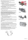
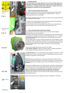
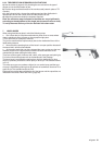
5.7 CANNON BLOWER GROUP
The cannon blower group is equipped with a multiplier similar to the normal axial
blower groups and all of its operating characteristics are the same.
The main difference with respect to the axial blower groups is that the
centrifugal fan rotor is made of galvanised steel, the fan rotors in this type are
fixed and can’t be adjusted, for the clutch see the previous paragraph. This fan
rotor can usually produce a delivery which is much higher with a very high
speed airflow (Fig. 25).
The cannon fan is mounted on a thrust block that can be adjusted by hand by
unscrewing the relevant locking screw. This adjustment must be done with the
fan rotor stopped because the high speed of the air make the movement of the
fan dangerous.
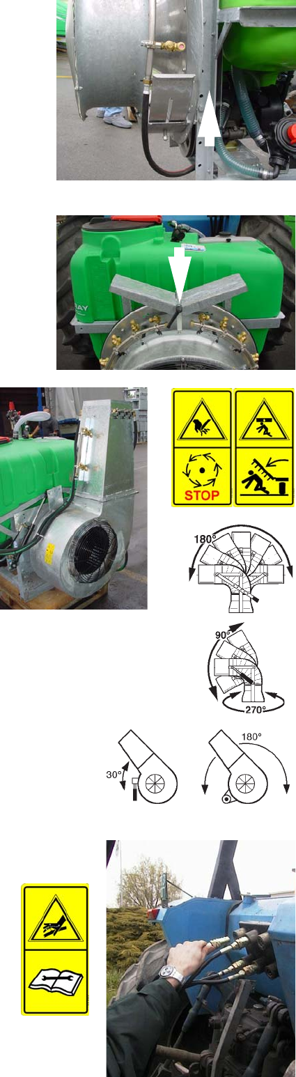
5.7.1 MANUALLY INCLINABILE HEAD
The cannon blower group can be equipped with a pivoting head (max inclination
180°) adjustable by hand.
5.7.2 HYDRAULIC DRIVEN HEADS
On request hydraulic pivoting (inclination 90° roughly) and rotating (max rotation
270°) heads are available.
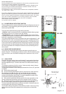
5.7.3 HYDRAULIC DRIVES
The cannon fans can be equipped with hydraulic drives: with the cylinder fitted
directly (30° inclination roughly) or a motor with a pinion and chain (180°
inclination roughly).
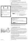
5.7.4 OIL FEED FROM TRACTOR
(for hydraulic systems)
Connect the delivery and discharge quick-fit coupling to the respective
connections, respecting the direction of flow.
The distributor inlet pipe is connected to the aluminium flow separator valve
next to the distributor.
The flow separator must be adjusted correctly so it sends less than 4-5 L/1° to
the distributor.
To prevent the cylinders moving at a dangerous speed, adjust the relevant
chokes near the cylinders. If the registration ringnuts aren’t visible then fixed
chokes are fitted. The chokes are fitted on the discharge line of the movement
to slow.
Any impurities in the oil could block the chokes and as a consequence block
the cylinder; remove the dirt if necessary. The maximum pressure valves of the
distributors are regulated to a pressure of around 150 bar.
FIG. 23
FIG. 24
FIG. 25