


It is suggested that this manual be read in its
entirety before attempting to assemble or
operate. Keep this manual in a safe place for
future reference and for ordering
replacement parts.
This unit is shipped WITHOUT GASOLINE
or OIL. After assembly, service engine with
gasoline and oil as instructed in the separate
engine manual packed with your unit.
NOTE: Ref er ence to right or left hand
side of the mower is ob served from the
op er at ing po si tion.
UNPACKING
RE MOVING UNIT FROM CAR TON
• Re move sta ples, break glue on top flaps, or
cut tape at car ton end and peel along top
flap to open.
• Re move loose parts in cluded with unit (i.e.,
op er a tor’s man ual, oil, etc.).
• Cut cor ners and lay car ton down flat. Re -
move pack ing ma te rial.
• Roll or slide unit out of car ton. Check car ton
thor oughly for loose parts.
CAU TION: DO NOT BEND OR KINK
CA BLES.
TOOLS RE QUIRED
Pair of Pli ers Fun nel
ASSEMBLY
CAUTION: DISCONNECT SPARK
PLUG WIRE. IF THE WIRE IS NOT
EQUIPPED WITH A RUBBER BOOT,
SEE SEPARATE ENGINE MANUAL
FOR GROUNDING PROCEDURE.
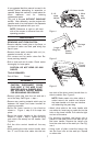
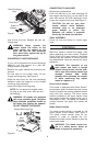
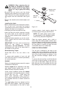
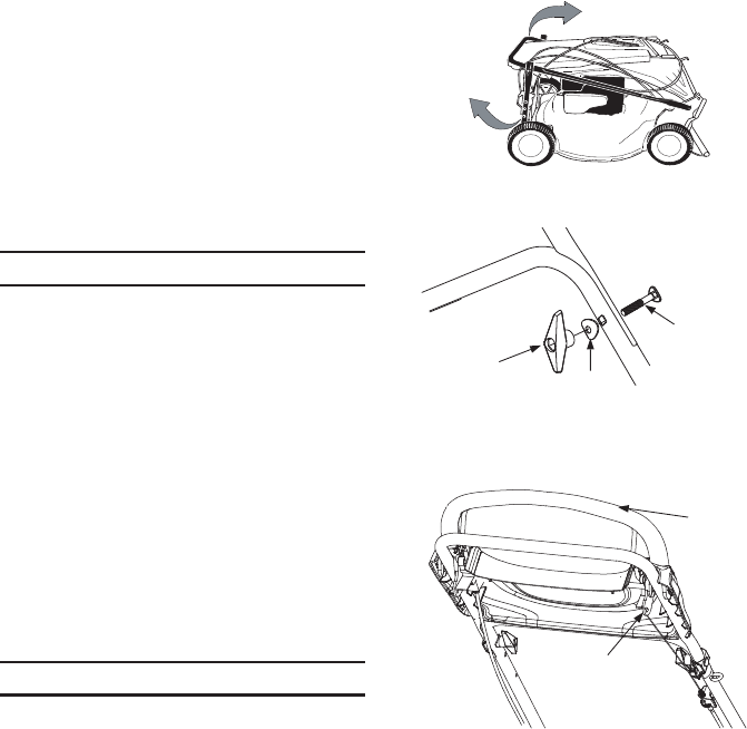
• Re move grass bag from the unit and set it
out of the way. See Fig ure 1, step 1.
• Re move any pack ing ma te rial which may be
be tween the up per and lower han dles for
ship ping pur poses.
• Raise the lower han dle in the di rec tion
shown in Fig ure 1, step 2 till it snaps into
place.
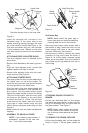
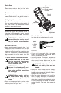
• Raise the up per han dle in the di rec tion
shown in Fig ure 1, step 3. Tighten the wing
nuts which are al ready on the han dle. See
Fig ure 2.
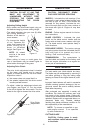
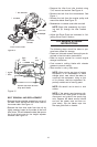
• Pull the drive con trol han dle all the way
back.
• While hold ing the drive con trol han dle, hook
the “Z” end of the drive ca ble into the bot -
tom hole of the drive con trol han dle from in -
side to out side. See Fig ure 3.
NOTE: Make cer tain the drive ca ble is
routed around the out side and above
the lower han dle so it does not in ter fere
with at tach ing the grass bag.
• At tach drive ca ble to the lower han dle with
one ca ble tie. In sert peg on ca ble tie into the
hole on the lower han dle. Pull ca ble tie tight
and cut off the ex tra.
• For ship ping pur poses, the hair pin clip is
placed in the outer hole of the weld pin on
the lower han dle. Re move the hair pin clip
from the outer hole of the weld pin. See Fig -
ure 4.
• Using a pair of pli ers, in sert the hair pin clip
into the in ner hole on the weld pin. Re peat
on other side.
7
Fig ure 1
2 Lift lower han dle.
3 Lift
up per
han dle.
1 Move
bag
away.
Fig ure 3
Drive
Control
Handle
Insert "Z"
fittiing
Figure 2
Large
Wing Nut
Saddle
Washer
Carriage
Bolt