


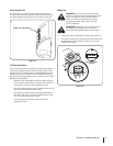
Checking Oil Level
CAUTION: The engine is shipped with oil in the
engine. You must, however, check the oil level prior
to operating the snow thrower. Running the engine
with insufficient oil can cause serious engine
damage and void the engine warranty.
NOTE: Be sure to check the engine on a level surface with the
engine stopped.
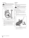
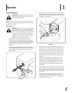
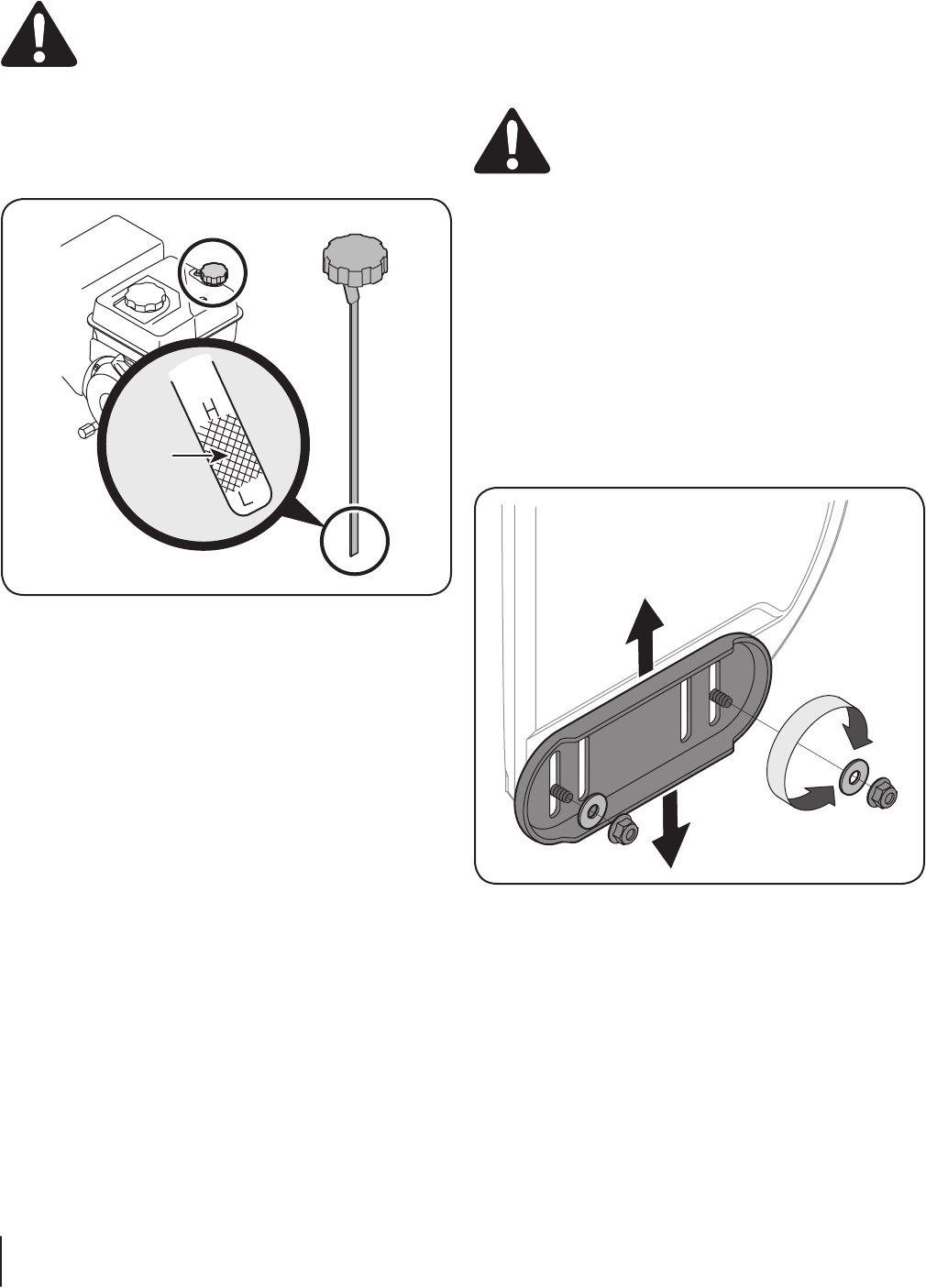
Remove the oil filler cap/dipstick and wipe the dipstick 1.
clean. See Fig. 3-9.
Insert the cap/dipstick into the oil filler neck, but do 2. not
screw it in.
Remove the oil filler cap/dipstick. If the level is low, slowly 3.
add oil until the oil level registers between high (H) and low
(L), Fig. 3-9. Refer to the Engine Maintenance section for
the correct oil viscosity and engine oil capacity.
NOTE: Do not overfill. Overfilling with oil may result in
engine smoking, hard starting or spark plug fouling.
Replace and tighten the cap/dipstick firmly before starting 4.
the engine.
Adjustments
Skid Shoes
The snow thrower skid shoes are adjusted upward at the factory
for shipping purposes. Adjust them downward, if desired, prior
to operating the snow thrower.
CAUTION: It is not recommended that you operate
this snow thrower on gravel as it can easily pick up
and throw loose gravel, causing personal injury or
damage to the snow thrower and surrounding
property.
For close snow removal on a smooth surface, raise the skid shoes
higher on the auger housing.
Use a middle or lower position when the area to be cleared is
uneven, such as a gravel driveway
NOTE: If you choose to operate the snow thrower on
a gravel surface, keep the skid shoes in position for
maximum clearance between the ground and the shave
plate.
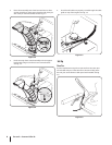
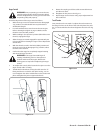
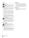
To adjust the skid shoes:
Loosen the four hex nuts (two on each side) and carriage 1.
bolts. Move the skid shoes to the desired position. See Fig.
3-10.
Make certain the entire bottom surface of the skid shoe is 2.
against the ground to avoid uneven wear on the skid shoes.
Retighten the nuts and bolts securely.3.
Fill
between
high
and low
marks
Figure 3-9
Figure 3-10
10 se c t i O n 2— as s e M b l y & se t-up