


Section2: Assembly
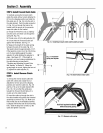
3. Usea cabletie (EE,Fig.2-9) to fasten
the reverseclutch cableto the left side
handlebar.
4. Test the function of the reverseclutch
cable by pulling the knob out and
releasingit. The knobshould return to its
neutral position (resting against bracket)
when it is released. If it doesn't, contact
your local dealer or the factory for
technical assistance.
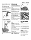
BB
DD
Flat Side
Fig. 2-8: Install reverse cablemounting
bracketand the reverse clutchcable.
CC
Fig. 2-9: Routereverse clutchcable (CC)as
shown. Attachto handlebar withcable tie
(EE).
STEP6: CheckLevelof
TransmissionGearOil
The transmission was filled with gear oil
at the factory. However,you should check
the gear oil levelto makecertain it is
correct.
IMPORTANT:Do not operate the tiller if
the gear oil level is low. Doingso will
result insevere damageto the transmis-
sign components.
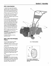
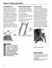
1. Put the tiller on levelground. Pullthe
DepthRegulator Lever (FF, Fig.2-10)
backand then adjust it up or down to the
notch that makesthe tiller level.
2. Removethe oil fill plug (GG,Fig. 2-11)
from the transmission housing and look
into the oil fill hole. You will seethe main
drive shaft on oneside of the hole.
3. The gear oil level iscorrect if the gear
oil is approximately halfway up the side of
the drive shaft.
4. If the gear oil level is low, add gear oil
by referring to "A. To ChecktheTransmis-
sion GearOil Level" in Section 5.
STEP 7: Add Motor Oil to Engine
Thetiller is shippedwithoutoil in the
engine.
IMPORTANT:Do not start the engine
without first adding motor oil. Severe
engine damagewill result ifthe engine is
run without oil.
1. Referto the EngineOwner's Manual
(supplied with tiller) for engine oil specifi-
cations and capacities.
2. With the tiller on level ground, pull the
DepthRegulator Lever (FF, Fig.2-10)
backand then slide it up or down as
necessaryuntil the engine is level.
3. Add motor oil as described in the
EngineOwner's Manual.
4. Movethe Depth RegulatorLeverall the
way down until the highest notch is
engaged. This placesthe tines in the
"travel" position.
Fig. 2-10: AdjustDepthRegulator Lever.
Fig. 2-11: Removegear oil fill plug.
STEP 8: Check Hardware for
Tightness
Checkall nuts and screws for tightness.
STEP9: CheckAir Pressurein
Tires)
Usea tire pressuregaugeto check the air
pressure in both tires. Deflateor inflate
both tires equally to 15-to-20 PSI
(pounds per square inch). Besure that
both tires are inflated equallyor the unit
will pull to one side.
IMPORTANT:This completesthe
assembly steps. Beforeoperating your
tiller, make sureyou readthe following
Sections in this Manual, aswell as the
separateEngineOwner's Manual:
• Section 1: "Safety"
• Section3: "Featuresand Controls"
• Section 4: "Operation"