


Section5: Maintenance
WARNING Beforeinspecting,cleaning or servicingthe unit, shut off engine, wait for all
partsto cometo a completestop, disconnectsparkplug wire and move wire away from spark
plug. Failure to follow these instructions can result in serious personal injury or
propertydamage.
B. To Drainthe TransmissionGear Oil:
DANGER
Gasoline is highly flammable
and its vapors explosive. Fol-
low these safety practices to
prevent injury or property
damage from fire orexplosion.
,, Allow the engine and
muffler to cool before
draining the tiller's gasoline
tank.
,, Do not allow open flames,
sparks, matches or smoking
in the area.
,, Wipe away spills and push
tiller away from spilled fuel.
,, Use only an approved fuel
container and store it safely
out of the reach of children.
,, Do not store gasoline where
its vapors could reach an
open flame or spark, or
where ignition sources are
present (such as hot water
and space heaters, furnaces,
clothes dryers, stoves,
electric motors, etc.)
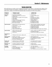
The transmission gear oil does not need
to bechanged unless it has beencontam-
inatedwith dirt, sand or metal particles.
1. Drain gasoline from the fuel tank or
run the engine until the fuel tank is empty.
See"DANGER"statement above.
2. Drain the oil from the engine.
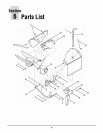
3. Removethe four screws (B, Figure5-2)
and washersfrom the transmission cover
and remove the cover and gasket.
4. Removethe left-sidewheel.
5. Tilt the left-side wheel shaft into a
drain panand allow the gear oil to drain
through the top of the transmission.
6. After draining oil, reinstall the wheel,
install a new gasket (do not reuseold
gasket) and screw on transmission cover.
7. Refill transmission using GL-4gear oil
(SAE85W-140 or SAE140).
8. Refill theengine with motor oil and
replenishthe fuel tank with gasoline.
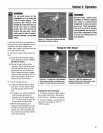
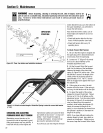
Figure5-2: Removeoilfi// plug(A)tocheck
gearoil/eve/and toaddgearoil. Remove
fourcoverscrews(B) todraingearoil.
TINES
The tines wear with use and they should
be inspectedat the beginning of each
tilling seasonand after every30 operating
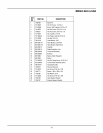
hours. Thetines can be replaced individ-
ually or as a complete set. Referto the
Parts List Section of this manualfor tine
identification information.
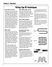
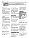
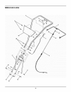
WARNING
This is a CRT (counter-rotating
tine) tiller and its tines must
be mounted in the direction
shown in Figure 5-3. If
mounted with curves in the
opposite direction, tiller will
dig poorly and be more likely
to run backward.
Failure to comply could result
in personal injury or property
damage.
NOTE:You mustfirst removethe tiller
hood before removing either a single tine
holder or individual tines. Removethe
two screws at thefront of the hood and
the two screws atthe rear of the hood
and lift off the hood. Besureto replace
the hood securelyafter changing a tine or
tine holders.
A. Tine Inspection:
With use,the tines will becomeshorter,
narrower and pointed. Badly worn tines
will result in a loss of tilling depth and
reducedeffectiveness in general, and
specifically when chopping up and
turning under organic matter.
B. Removingand Installing
Tine Assemblies
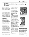
1. Usea 9/16" socket, 6" extension, a
ratchet,and a 9/16" box end wrench to
loosen the nut (A, Figure 5-3) and screw
(B) that secure the tine holder to the tine
shaft.
2. Usea rubber mallet to tap thetine
holder loose. Slide tine assembly off.
3. RepeatSteps 1 and 2 aboveto remove
the other tine assembly.
4. Installing the tine assembly issimply
the reverseof its removal. First besure
to removeany rust, unevenspots or burrs
from the tine shaft using fine sandpaper.
Then greasethe tine shaft before rein-
stalling the tine assemblies. Besure all
the cutting edgesface so they will enter
the soil first when the tiller is moving
forward- this meansthe cutting edge on
the top of each tine faces towardthe
operator position. Tighten hardware.
C. Removingand Installing
IndividualTines
1. Usetwo 9/16" box end wrenchesto
removethe two screws (C, Figure5-3)
and nuts (D) that securethe tine to its
tine holder.
NOTE:If the nuts are rusted,apply pene-
trating oil, then loosen the hardware.
2. When installing individual tines, do so
in the reverseorder from which they were
removed. The two sets of inboard tines
are installed so one set facestoward the
transmission andthe otherfacesaway
from it. The single outboardtine set
faces toward thetransmission housing.
Also be sure the cutting edge at the top
of each fine faces toward the operator
position. (SeeFigure 5-3.)
21