


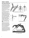
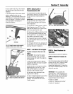

STEP 2: Attach Handlebar
1. Attach the two legsof the handlebar
support (A, Fig.2-2) loosely to the inner
sides of thetiller frame using two 3/8"-16
x 3/4" hex hd. screws (B), two 3/8" flat
washers (C)and 3/8"-16 hex Iocknuts (D).
2. Using using two 5/16"-18 x 1-1/2" hex
hd. screws (G), 5/16"split Iockwashers
(H) and 5/16"-18 hex nuts (I), loosely
attach thethe handlebarsupport (A) using
the upper holes.
3. There are three height adjustment holes
in the two handlebarsupport brackets. E
& F, Fig.2-2). Usea setting that will
position the handlebarsat approximately
waist level whenthe tines are 3"-4" into
the soil. Looselyattach the handlebar
support bracketstothe outsideofthe
handlebarassembly (K) using two 5/16"-
18 x 1-1/2" screws (G),5/16" split lock-
washers (H) and 5/16"-18 hex nuts (I).
NOTE:If a support bracketwill not move,
loosen attaching screw (J) and nut.
IMPORTANT:Thesupport brackets must
be assembledto the outsideof the
handlebarassembly.
4. Tighten all handlebar mounting
hardware securely.
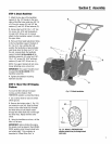
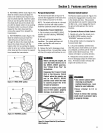
STEP 3: Move Tiller Off Shipping
Platform
To move the tiller without the engine
running, put the wheels in their
FREEWHEELposition, asdescribed below.
1. Usea sturdy block to raise onewheel
off the ground.
2. Removethe hairpin cotter (L, Fig.2-3)
and wheeldrive pin (M). Slide thewheel
inward on the wheelshaft (N). Reinstall
the wheel drive pin and hairpin cotter
through the wheel shaft only (not through
the wheel hub). Repeatwith the other
wheel.
3. Using the handlebaras a lever, roll the
tiller to aflat area.
IMPORTANT:Before starting the engine,
the wheels must be placedin their WHEEL
DRIVEposition (pins through wheel hubs
and wheelshaft). This procedureis
described in "Wheel Drive Pins" in
Section2: Assembly
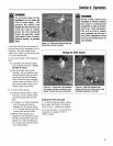
Fig. 2-2: Attach handlebar.
Fig. 2-3: Wheel in FREEWHEELING
position (wheel drivepin throughwheel
shaftonly).