


n
Assembly
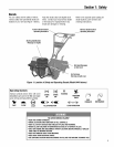
WARNING
To prevent personal injury or
property damage, do not start
the engine until all assembly
steps are complete and you
have read and understandthe
safety and operating instruc-
tions in this manual.
Introduction
Carefullyfollow these assembly stepsto
correctly prepareyour tiller for use. It is
recommendedthat you read this Section
in its entirety before beginning assembly.
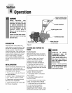
NOTE: Enginesyles vary by model. The
engineon your tiller may appeardiffer-
ently thanthose shown in illustrations
and Figuresthroughout this manual.
Inspectunit
Inspectthe unit and carton for damage
immediately after delivery. Contactthe
carrier (trucking company) if you find or
suspect damage. Inform them of the
damageand request instructions for filing
aclaim. To protect your rights, put your
claim in writing and mail acopy to the
carrier within 15 days after the unit has
beendelivered.
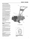
STEP 1: Unpacking Instructions
1. Removeany cardboard inserts and
packagingmaterial from the carton.
Removeany staplesfrom the bottom of
the carton andthen lift the carton up and
off the unit.
2. Thetiller is heavyand you should not
attempt to remove itfrom the shipping
platform until the handlebarsare
installed. The procedure for removing the
tiller is explainedin Step 3 of these
assemblysteps.
NOTE:Becareful not to severely bendany
of the control cables on the unit.
3. Removeall unassembled parts and
the separatehardware bagfrom the
carton. Checkthat you havethe items
listed below (contact your local dealeror
the factory if any items are missing or
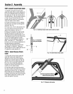
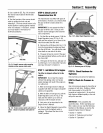
damaged). NOTE: Usethe screw length
template (Fig. 2-1) to identify screws.
LoosePartsList
Qty. Description
1 HandlebarSupport (seeA, Fig.2-2,
page7)
1 HandlebarAssembly
(see K, Fig.2-2)
Thefo//owing itemsare in the
hardware bag:
4 Hexhd. screw, 5/16-18 x 1-1/2"
2 Hexhd. screw, 3/8-16 x 3/4"
2 Flatwasher, 3/8"
4 Split Iockwasher,5/16"
4 Hexnut, 5/16"-18
2 HexIocknut, 3/8"-16
IMPORTANT:Motoroil mustbe addedto
the enginecrankcasebeforethe engine
is started. Followthe instructionsinthis
"Assembly" section.
NOTE:LEFTand RIGHTsides of the tiller
are asviewed from the operator's
position behindthe handlebars.
Tools/MaterialsNeededfor
Assembly
(2) 1/2" open-endwrench*
(1) 3/8" open-endwrench*
(2) 9/16" open-endwrench*
(1) Largeadjustable wrench
(1) Scissors (to trim plasticties)
(1) Ruler (for belt tension check)
(1) Block of wood (to support tiller
when removing wheels)
(1) Automotive-type air pressure gauge
(1) Cleanoil funnel
(1) Clean,high-quality engine oil. Refer
to the EngineOwner Manual for
engine oil specifications and quantity
required. Do not overfill.
* Adjustable wrenchesmay be used.
Figure2-1: Toidentifylength ofscrew,
placescrewontemplateasshownand
measuredistancebetweenbottomofscrew
headandtipofscrew.