


16
.
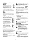
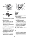
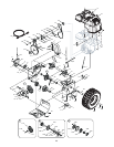
Figure 23
Figure 24
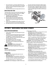
9. Reassemble new friction wheel rubber to the
friction wheel assembly, tightening the four screws
in rotation and with equal force. See Figure 24.
IMPORTANT:
Assemble the rubber on the friction wheel
equally for proper functioning.
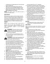
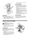
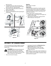
10. Insert the shift arm assembly into the friction wheel
assembly and hold assembly in position. See
Figure 25.
11. Slide hex shaft through right side of the housing
and the friction wheel assembly.
12. Insert the hex shaft through the sprocket and the
spacer. Make certain that chain engages both the
large and the small sprocket.
NOTE: If the sprocket fell from the snow thrower while
removing the hex shaft, place the sprocket on the hex
shaft. Position the hex hub of the sprocket toward the
friction wheel when sliding the sprocket on to hex shaft.
13. Align the hex shaft with the left bearing and
carefully guide this bearing into left side of housing.
14. Install the right bearing on the hex shaft and check
that the spacer and bearing in the drive cover are
aligned to the steerable shaft. See Figure 25 .
15. Reassemble the drive cover with four screws
removed in step 6. Install the right wheel with the
bolt removed earlier.
16. Reassemble the frame cover with the two self-
tapping screws. Flip the equipment back to the
operating position and re-attach the belt cover.
Figure 25
NOTE: If you placed plastic under the gas cap, be
certain to remove it.
Adjustments
Drive Clutch
Refer to the Final Adjustment section of the Assembly
instructions to adjust the drive clutch. To check the
adjustment, proceed as follows:
• Drain the gasoline out of your snow thrower’s
engine, and place a piece of plastic film under the
gas cap to avoid spillage.
• Tip the snow thrower forward, allowing it to rest on
the auger housing.
• Remove the frame cover underneath the snow
thrower by removing self-tapping screws.
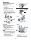
• With the traction control released, check if there is
1/8” clearance between friction wheel and drive
plate in all positions of the shift lever.
• With the traction control lever engaged, check if the
friction wheel solidly contacts the drive plate. See
Figure 21. If not, adjust as follows:
• Loosen the jam nut on the traction drive cable and
thread the cable in or out as necessary.
• Retighten the jam nut to secure the cable when
correct adjustment is reached.
17. Reassemble the frame cover.
NOTE: If you placed plastic under the gas cap, be
certain to remove it.
Auger Clutch
Refer to instructions on page 6 to adjust the auger
control.
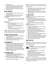
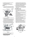
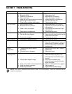
Shift Rod
To adjust the shift rod, proceed as follows.
1. Place shift lever in the fastest forward speed. See
Figure 26A.
2. Remove hairpin clip from the shift handle under the
handle panel. See Figure 26B.
3. Push shift arm assembly down as far as it will go.
Sprocket
Bearing
Screw
Friction
Wheel
Rubber
Plate
Friction
Hex Shaft
Shift
Arm
Wheel