


Assembly
8
Section
2
IMPORTANT: Follow the assembly steps
carefully. Contact the factory or your
local authorized dealer if you have any
questions or problems.
A. Inspect Unit
Inspect the unit and shipping crate for
damage immediately after delivery.
Contact the carrier (trucking company) if
you find or suspect damage. Inform them
of the damage and request instructions
for filing a claim. To protect your rights,
put your claim in writing and mail a copy
to the carrier within 15 days after the unit
has been delivered. Contact the factory as
indicated on page 3 of this manual if you
need assistance.
B. Tools/Materials Required for
Assembly
(1) Crowbar or large screwdriver (to
disassemble wood crate)
(1) Scissors or knife (to cut plastic ties)
(1) *5/16" wrench
(1) *3/8" wrench
(2) *7/16" wrenches
(2) *1/2" wrenches
(1) *9/16" wrench
(1) Phillips head screwdriver (medium)
(1) Needle-nosed pliers (medium)
(1) Automotive-type tire pressure gauge
(1) Funnel
(1) Clean, high-quality motor oil. Refer to
the separate engine owner’s manual
for the exact oil specifications and
amount needed for your engine.
* Adjustable wrenches may be used.
IMPORTANT: Motor oil must be added to
the engine crankcase before the engine
is started. Follow the instructions in this
“Assembly” section.
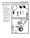
D. Hardware Bag Contents
The hardware bag should contain the items
listed below and shown in Fig. 2-2:
*These items are extra auger shear bolts
and locknuts (if the auger catches a hard
obstruction, the shear bolts are designed
to break to prevent damage to the auger
and other parts). See the “Maintenance”
section for replacement steps.
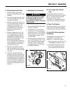
C. Unpacking Instructions
The shipping crate should contain:
• Snowthrower/engine/auger assembly
• Handlebar assembly
• Discharge chute assembly
1. Remove top and sides of wood crate.
2. Remove discharge chute assembly
(with attached hardware bag) from
inside cardboard sleeve. Remove
cardboard sleeve.
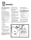
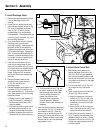
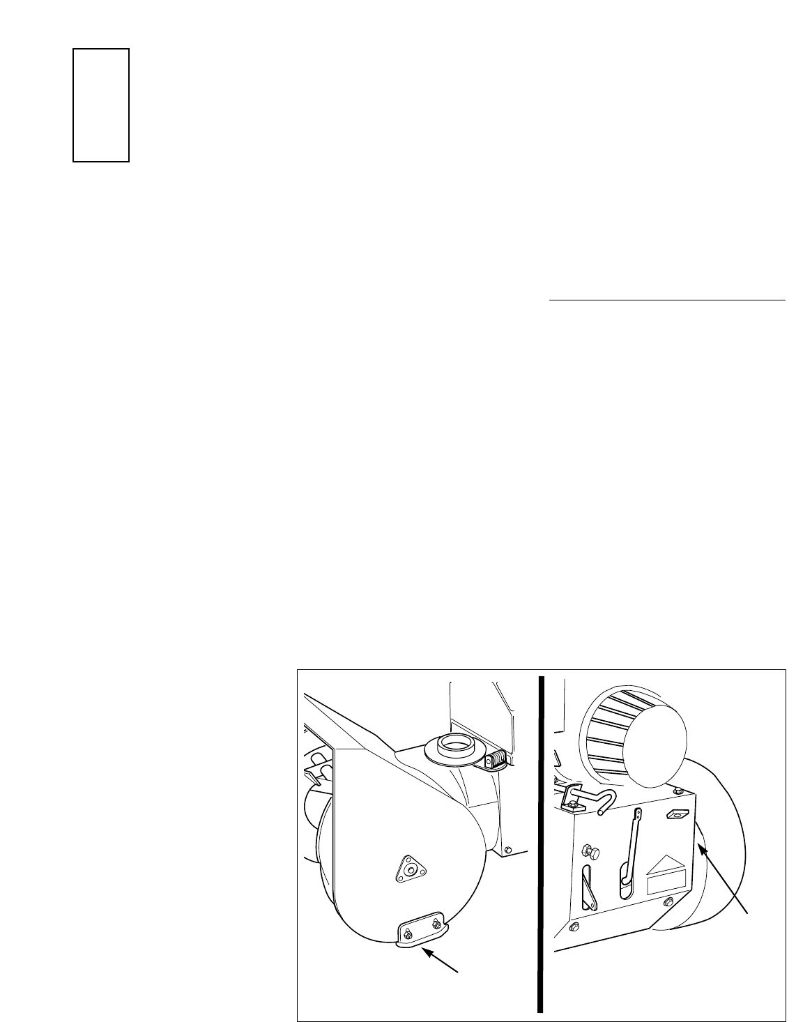
3. Remove the hex nut (A, Fig. 2-1) and
the shipping strap from the left side
skid shoe. Reinstall the hex nut,
tightening it securely.
4. Remove the screw (B, Fig. 2-1) and the
shipping strap from the rear cover on
the right side of the unit. Reinstall the
screw, tightening it securely.
5. The unit is heavy. Use caution and
obtain the help of at least one
assistant. Carefully remove the unit
from the crate by rolling the unit off the
platform. Park the unit on a clean, level
surface.
Ref. Description Qty.
A Cable tie ...................................... 3
B Hex hd. flange screw, 3/8-16 x 3/4 4
C Hex hd. screw, 1/4-20 x 3/4........... 2
D Locknut, 1/4-20............................. 2
E Phillips hd. screw, #10-24 x 3/8 ... 2
F Locknut, #10-24 ............................ 2
G Cotter pin ...................................... 1
H *Shear bolt, 5/16-18 x 1-3/4 ......... 2
I *Locknut, 5/16-18......................... 2
J Ignition key.................................... 2
-- Grease Tube (not illustrated). For
maintenance use if required......... 1
Fig. 2-1
B
A
Remove Rear Shipping Strap.