


13
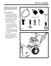
Section 2: Assembly
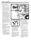
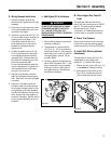
K. Wiring Harness Installation
1. Remove the plastic cable tie that
secures the wiring harness to the right
handlebar.
2. Route the wiring harness to the inside
of the right handlebar and over to the
right side of the engine.
3. Attach the ring terminal (AK, Fig. 2-10)
on the two black wires to the screw on
the engine shroud as shown. The
lockwasher should be next to the
screw head and the ring terminal in
between the lockwasher and the
engine shroud.
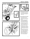
4. Connect the spade terminal (AL, Fig.
2-10) on the black wire to the yellow
wire receptacle inside the connector
receptacle (AM). Note that there are
two yellow wires extending out of the
back of the receptacle (AM).
Do not install the spade terminal (AL)
into the receptacle for the yellow wire
that is attached with a small plastic
connector to the red wire.
5. Plug the wiring harness connector
(AN) into the engine connecting plug
(AO). Note that it can only be plugged
in one way.
6. Using two of the plastic cable ties
provided, loosely (to avoid stretching
wires) attach the upper section of the
wiring harness to the right handlebar.
Use the third cable tie to loosely tie the
black, blue and red wires together at
the side of the engine. Be sure that the
wires are positioned safely away from
the wheel.
M. Check Auger Gear Case Oil
Level
The auger gear case was filled at the
factory with the correct amount of SAE 90
gear oil. This level should be checked
before using the unit. Refer to
“Lubrication” in the Maintenance section
of this manual for complete information.
N. Check Tire Pressure
Check the air pressure in both tires using
an automotive-type tire pressure gauge.
Inflate tires evenly to 8-12 psi (55-82 kPa).
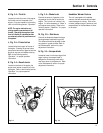
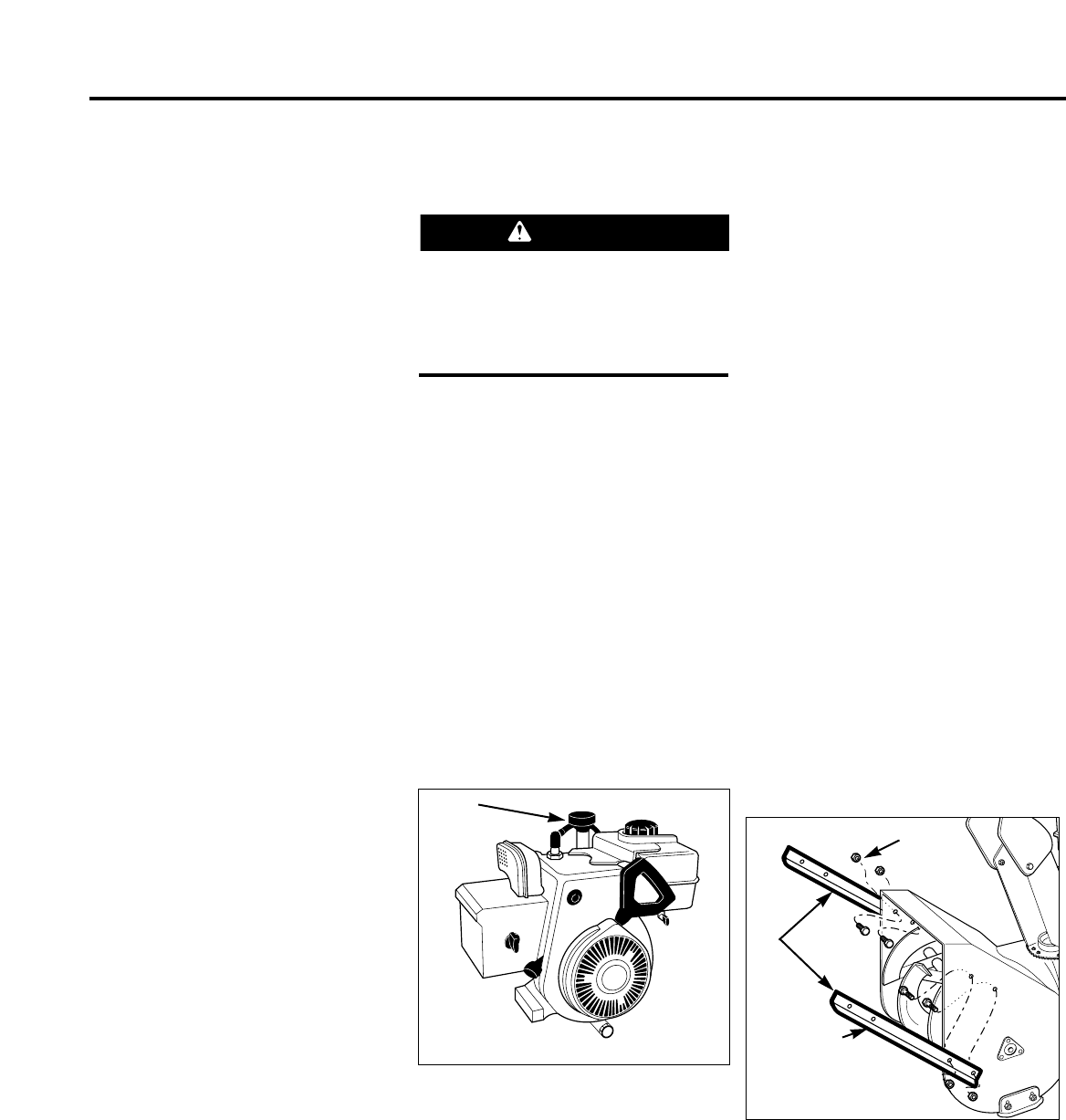
O. Install Drift Slicers (optional
attachment)
The optional drift slicers (AR, Fig. 2-12)
are designed for use in deep snow
conditions. To install the drift slicers:
1. Position the drift slicers (AR, Fig. 2-12)
to the outside of the auger housing.
2. Attach the drift slicers with the four
5/16–18 x 3/4 screws and locknuts
(AS) provided with the drift slicers.
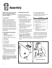
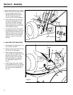
L. Add Engine Oil to Crankcase
1. Be sure that the engine is level before
checking or adding oil.
2. To add engine oil, unscrew dipstick
(AP, Fig. 2-11). Fill oil at the dipstick
opening with fresh oil. See the engine
owner manual for correct oil specifica-
tions and quantity required. Do not
use SAE 10W40.
3. Oil level on dipstick should always be
above “ADD” and below “FULL”. Wait
a few minutes after filling crankcase,
allowing oil to settle. Insert dipstick
and tighten securely. Recheck level
and adjust as necessary.
WARNING
DO NOT START ENGINE UNTIL ENGINE
CRANKCASE HAS BEEN FILLED WITH
OIL. FAILURE TO FOLLOW THIS
INSTRUCTION WILL RESULT IN SERIOUS
ENGINE DAMAGE.
Fig. 2-11
AP
AR
AS
AS
Fig. 2-12