


25
Section 5: Maintenance
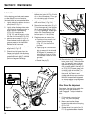
5. Remove the auger drive belt from the
lower drive pulley (AO).
6. Remove the belt from unit.
To install the auger drive belt:
1. Position the auger drive belt (AD)
down through gap. Position the belt
into the lower drive pulley (AO).
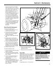
2. Position the auger drive belt (AD) into
pulley (AE). Reinstall the belt guide
(AC) and secure.
3. Reinstall bolt (BD), leaving 1/16"
(1.5mm) clearance between underside
of bolt head and front edge of pulley
(AE). Tighten jam nut (BC) against
engine crankcase.
4. Perform the auger drive belt
adjustment as necessary.
5. Reinstall the belt cover and bolts.
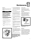
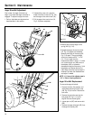
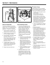
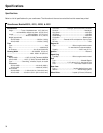
Slip Differential Adjustment
1. On right side of unit, remove hub cap
(AQ, Fig. 5-12) at end of wheel axle
shaft. Remove outer (AR) and inner
jam nuts (AS) and both pairs (four
single disk springs) of disk springs
(AT). Inspect springs and replace them
if they are worn.
2. Reinstall disc springs (AT) and inner
jam nut (AS). Tighten jam nut (AS) by
hand until it contacts the disc spring,
then tighten (AS) 1 to 1-1/4 turns
more. DO NOT force nut more than 1-
1/4 turns or differential will not work.
3. Secure the inner nut (AS) in place,
while tightening the outer nut (AR).
4. Reinstall cover (AQ).
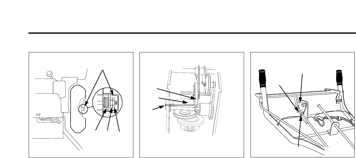
Gear Shift Rod Adjustment
1. Move the gear shift lever (AU, Fig. 5-9)
to position No. 5. Remove the hairpin
cotter and the flat washer from the
pivot block (N, Fig. 5-14). Disconnect
the pivot block (N) from the gear shift
lever plate (AV, Fig. 5-14).
2. Pull the gear shift control rod (AA, Fig.
5-10) down completely.
3. While holding the gear shift control rod
down (AA), loosen the jam nut (ZZ, Fig.
5-14) and thread the pivot block (N) up
or down as needed so it fits into the
hole in the gear shift lever plate (AV).
4. Reinstall the pivot block into the gear
shift control lever hole and secure with
the washer and hairpin cotter. Secure
the jam nut (ZZ) against the pivot
block (N).
5. Move the gear shift control lever (AU,
Fig. 5-9) through the full range of
travel. Check for binding. Refer to the
drive disk clearance adjustment below,
if needed.
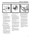
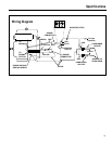
Drive Disc Clearance Adjustment
If the gear shift rod lever does not move
freely through all the gear positions,
adjust clearance (AY, Fig. 5-13) as follows:
1. Loosen the jam nut (AW, Fig. 5-10).
Rotate the adjusting screw (AX) until
the rubber drive wheel (T, Fig. 5-13)
contacts the metal drive disk (U).
2. Turn the rubber drive wheel (T) and
the metal drive disk (U) to find the
point of minimum clearance (AY).
(This is where both the drive wheel [T]
and metal disk [U] are touching.)
3. Adjust the disks at the point of
minimum clearance. Loosen adjusting
screw (AX) 1/2 turn. Secure the
adjusting screw (AX) in place, while
tightening the jam nut (AW).
4. Check the clearance (AY, Fig. 5-13) by
moving gear shift lever (AU, Fig. 5-9)
through all positions. Repeat step 3
as necessary.
Fig. 5-12 Fig. 5-13
AQ
AT
AS
AR
AY
T
U
Fig. 5-14
N
AV
ZZ