


7
Figure 6
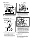
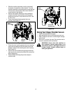
• Place the four straps on the top of the bag over
upper handle, hooking them on the studs to secure
in place. Squeeze the clamp on the drawstring and
pull the drawstring tight. Release the clamp.
See Figure 7.
Figure 7
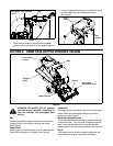
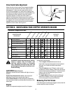
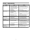
SECTION 3: KNOW YOUR CHIPPER SHREDDER VACUUM
Figure 8
WARNING: Be familiar with all controls
and their proper operation. Know how to
stop the machine and disengage them
quickly.
Bag
Collects shredded or chipped material fed through the
chipper chute or vacuumed up through the nozzle.
See Figure 8.
Chipper Chute
Allow twigs and small branches up to 3” in diameter to
be fed into the impeller for chipping. See Figure 8.
Caster Locks
The caster locks are located on top of each front caster
wheel. Refer to the Adjustment Section to position
wheel locks. See Figure 8.
Nozzle Door Adjustment Levers
The nozzle adjustment levers are located on each side
of the nozzle door. They are used to adjust the nozzle
door for ground clearance that will provide the best
performance for the operating conditions. See Figure 8.
Nozzle
Yard waste such as leaves and pine needles can be
vacuumed up through the nozzle for shredding.
Discharge
Chute
Bag
Bag Opening
Bag
Straps
Bag
Straps
Drive Clutch
Control
Bag
Nozzle
Nozzle Door
Adjustment Lever
Chipper
Chute
Caster Locks