


Features and Controls
3
Section
KNOW YOUR EQUIPMENT
READ THIS OWNER’S MANUAL AND ALL SAFETY RULES BEFORE OPERATING YOUR EQUIPMENT. Know the
location and function of all features and controls on the equipment. Save this manual for future reference.
7
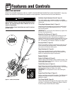
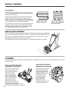
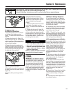
Handlebar Height Adjustment Knob (B, Figure 5)
Two height settings, plus a storage position are available.
Refer to Assembly Steps, STEP 1 in Section 2 for adjustment
instructions.
Tilling Depth Adjustment Knob (C, Figure 5)
Loosening the knob enables you to move the wheel bracket
(K) up or down on the height adjustment bar (L). This con-
trols the tilling depth.
IMPORTANT: Do not move the wheel bracket any higher than
the top of the adjustment bar.
Adjustable Tine Patterns (D, Figure 5)
The four tine sections are assembled at the factory for max-
imum performance under a wide variety of conditions. If
needed, the tines can be arranged for narrower tilling or close
cultivating. The tines can also be arranged to till very stony
soil. See
Adjusting Tine Patterns in Section 4 for details.
Carrying Handle (E, Figure 5)
When the handlebar is folded in the storage position the unit
can be carried by the carrying handle. The carrying handle
also serves as a tie-down anchor point.
Edger Attachment (H, Figure 5)
Use this separate attachment to create borders or edges
along walks, driveways, flower beds, etc. See Section 4 for
details on installing and using this attachment.
Engine Controls
Engine On/Off Switch (A, Figure 5)
Use the engine On/Off Switch to start or stop the engine. See
Starting and Stopping the Engine in Section 4 and the Engine
Owner’s Manual for details.
Throttle/Tines Lever (G, Figure 5)
Squeeze this lever to start tine rotation and to vary the tine
speed. Release the lever to stop all tine motion. See Starting
and Stopping the Engine
in Section 4 for details.
IMPORTANT: Do not squeeze this lever when starting the
engine.
Engine Recoil Start Rope (F, Figure 5)
Use the recoil start rope to start the engine. See Starting and
Stopping the Engine
in Section 4 and the Engine Owner’s
Manual for details.
Fuel Primer Bulb (M, Figure 5)
Use the fuel primer bulb to help start the engine under certain
conditions. See Starting and Stopping the Engine in Section
4 and the Engine Owner’s Manual for details.
Figure 5: Features and controls.
B
B
C
K
L
E
J
J
F
G
J
D
Before operating your machine, carefully read and under-
stand all safety, controls, and operating instructions in this
Manual, the separate Engine Owner’s Manual and on the
decals on the machine.
Failure to follow these instructions can result in serious
personal injury.
WARNING
H
A
M
ENGINE DETAIL