


If the engine is running poorly or has low
power while tilling, an adjustment to the
carburetor may solve the problem. How-
ever, first inspect and service the spark
plug and the air filter before making a
carburetor adjustment. If the engine con-
tinues to run poorly (and the fuel mixture
is fresh), proceed to the following carbu-
retor adjustment instructions.This fac-
tory-engineered instruction is designed to
provide continued optimum engine oper-
ating performance after the engine break-
in period, which is approximately 5 to 10
hours. The adjustment, when properly
performed as described below, will not
void the engine warranty. A common
screwdriver is needed. If you prefer, see
an authorized engine dealer for
adjustment.
Prior to Carburetor Adjustment:
1. Let engine cool for 30 minutes before
continuing.
2. From the operator’s position behind the
handlebars, lay the machine down on its
left side (muffler side).
Carburetor Adjustment:
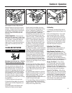
1. Locate the carburetor idle mixture
screw (Figure 15). It is directly under the
air filter and is black.
Do Not Adjust Silver-Colored Screw.
2.
Turn the black idle mixture screw 1/16
of a turn clockwise.
3. Return the unit to its normal upright
operating position and reconnect the
spark plug wire.
If the engine continues to run poorly, con-
tact an authorized engine dealer.
Spark Plug
Inspect the spark plug annually or every
100 operating hours according to the in-
structions in the separate Engine Owner’s
Manual. Check that the gap is set at .030".
For replacement use Champion RCJ-6Y or
equivalent (a resistor spark plug must be
used for replacement).
Cooling System
It is important to frequently check and
remove grass clippings, dirt and other
debris that accumulates on the engine,
cooling fins, air intake screen and on
levers and linkages. This helps to ensure
adequate air cooling and correct engine
speed.
TINE REMOVAL
AND INSTALLATION
The tines will wear with use and they
should be replaced if tilling seems to take
longer than usual or if the soil is not
being mixed as thoroughly. Also, in addi-
tion to the standard 10" tilling width tine
configuration, the tines can be arranged
in two other configurations: (1) A narrow,
4
1
/2" tilling width for smaller areas and (2)
A special pattern for stony soil conditions.
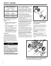
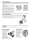
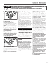
IMPORTANT: The hitch pin (A, Figure 16)
is under spring tension – wear gloves to
protect your fingers when removing or re-
placing the hitch pin.
Arranging Tines for Narrow Tilling
1. Prop the machine forward so it rests
on the front of the tubular carrying
handle. The work surface should be flat
and firm.
2. Remove the hitch pin (A, Figure 16).
3. Remove the outer tine section (do not
remove inner tine section) and mark it as
to which side it is from (left or right) and
whether it’s an outer or inner tine section.
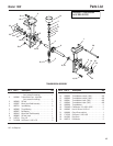
4. Slide one of the long bushings (B,
Figure 17), provided with the unit, onto
the shaft. Insert the hitch pin through the
tine shaft.
5. Repeat this procedure on the opposite
side.
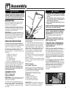
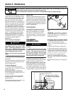
Figure 15: Idle Mixture Screw can be adjusted.
Fuel Tank
Primer Bulb
Primer Line
Idle Speed Screw (Silver)
Idle Mixture Screw (Black)
Fuel Line
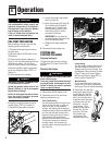
The temperature of the muffler and adja-
cent engine areas may exceed 150
o
F
(65
o
C). Contact may cause burns. Avoid
these areas. Remove the spark plug
lead and ground the lead to the engine to
prevent accidental starts and fires.
Failure to do this could cause personal
injury.
WARNING
Avoid contact with the cutting edges on
the tines.
To avoid personal injury when removing
or installing tines, wear heavy work
gloves. The engine must be off, all
moving parts stopped, and the spark
plug wire disconnected from the spark
plug and moved away from the plug.
WARNING
Section 5: Maintenance
12
Figure 16: Remove hitch pin (A) to take off
tines.
A
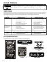
Before inspecting, cleaning or servicing the machine, shut off engine, wait for moving parts to stop, dis-
connect spark plug wire and move wire away from spark plug.
Failure to follow these instructions can result in serious personal injury or property damage.
WARNING