


16
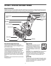
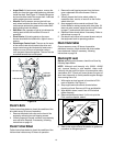
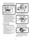
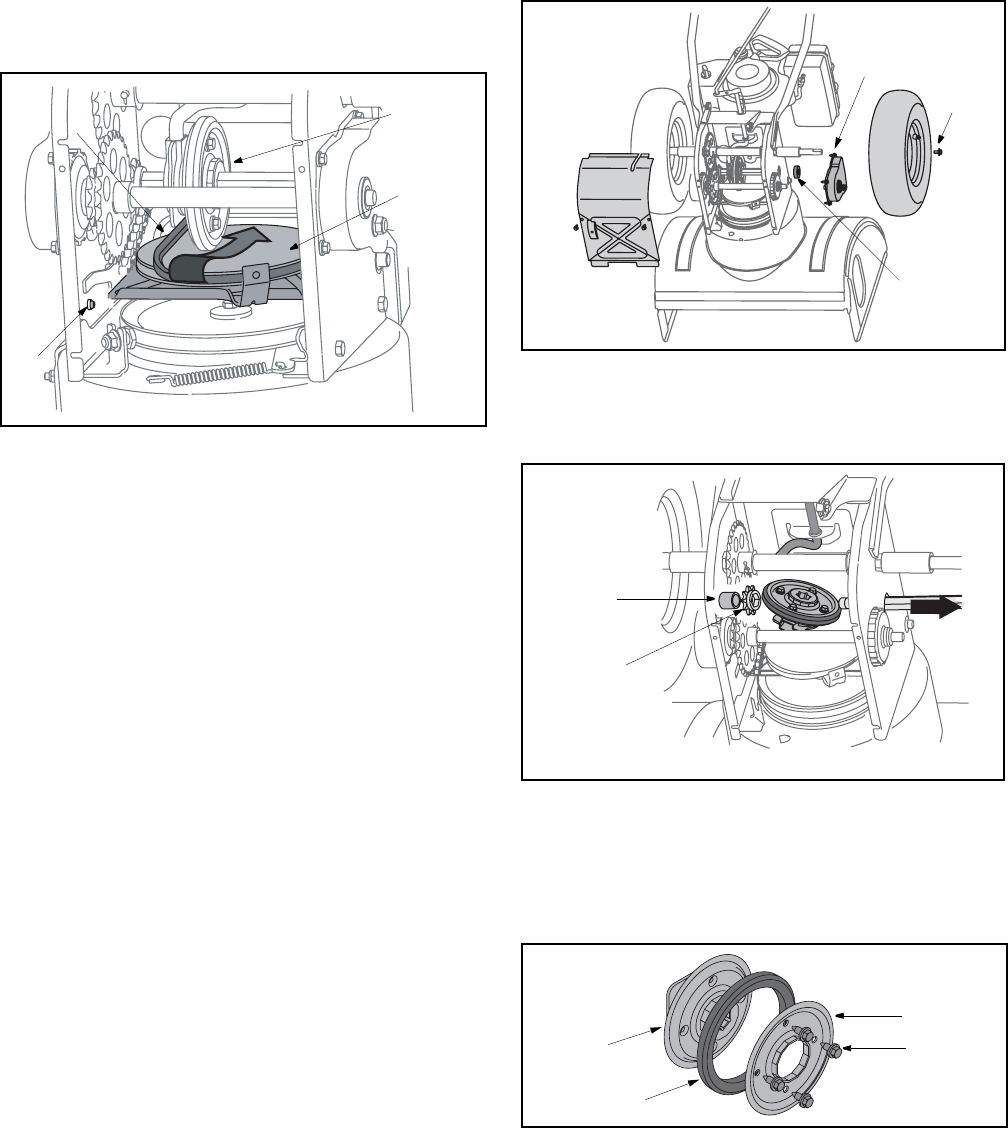
4. Back out the stop bolt to create sufficient gap
between the friction wheel disc and the drive pulley.
Pull the drive belt from around the drive pulley and
clear it off the friction wheel disc. See Figure 18.
Figure 18
5. Now moving to the other side of the snow thrower
again, slide the belt off the crankshaft.
6. Replace with new belt, first sliding it through the
crank shaft, then working it around the groove of
the drive pulley and finally wrapping it around the
engine pulley from where the old belt was removed.
Once the belt is firmly placed on the pulleys, make
sure to remove the screwdriver from the idler.
7. Re-install auger belt on the engine pulley.
8. Re-attach frame cover on the snow thrower
housing and put the equipment back to operating
position. Re-attach belt cover with two self-tapping
screws removed earlier.
Friction Wheel Rubber
1. Check the rubber on the friction wheel after 25
hours of operation, and periodically thereafter.
Replace the rubber if any signs of wear or cracking
are found.
2. Drain the gasoline from the snow thrower, or place
a piece of plastic under the gas cap. Move shift
lever to the R2 position.
3. Tip the snow thrower so that it rests on the housing.
Remove the self-tapping screws from the frame
cover underneath the snow thrower.
4. Remove bolt securing the right wheel, and remove
the wheel from the axle.
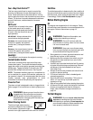
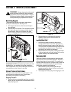
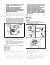
5. Remove the four screws securing the right drive
cover to the frame. Remove the drive cover from
the side of the frame. See Figure 19.
Figure 19
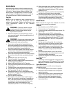
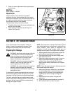
6. Holding the friction wheel assembly, slide the hex
gear shaft to the right. See Figure 20. The spacer
on right side of hex gear shaft may fall.
Figure 20
7. Lift the friction wheel assembly out between the
axle shaft and the drive shaft assemblies.
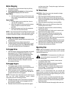
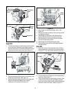
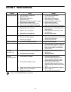
8. Remove the four screws from the friction wheel
assembly. Remove friction wheel rubber from
between the friction wheel plate. See Figure 21.
Figure 21
9. Reassemble new friction wheel rubber to the
friction wheel assembly, tightening the four screws
in rotation and with equal force. See Figure 21.
IMPORTANT:
Assemble the rubber on the friction wheel
equally for proper functioning.
Stop
Bolt
Drive Pulley
Friction
Wheel
Drive
Belt
Drive Cover
Bolt
Spacer
Sprocket
Bearing
Screw
Friction
Wheel
Rubber
Plate