Groundsmaster 4500--D/4700--D Hydraulic SystemPage 4 -- 99
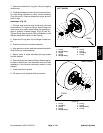
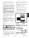
7. Remove and discard O--ring (item 16) from flange of
wheel motor.
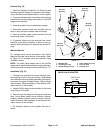
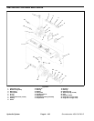
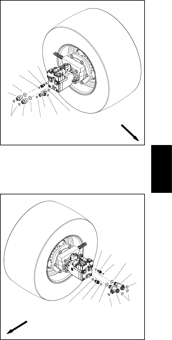
8. If hydraulic fittings are to be removed from wheel mo-
tor, mark fitting orientation to allow correct assembly
(Figs. 80 and 81). Remove fittings from motor and dis-
card O--rings.
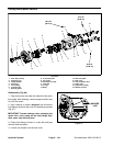
Installation (Fig. 79)
1. If fittings were removed from wheel motor, lubricate
and place new O--rings onto fittings. Install fittings into
motor ports using marks made during the removal pro-
cess to properly orientate fittings (Figs. 80 and 81).
Tighten fittings (see Hydraulic Fitting Installation in the
General Information section of this chapter).
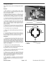
2. Place new O--ring (item 16) into flange of wheel mo-
tor.
3. Position wheel motor to brake assembly.
4. Align splines on motor shaft and splined brake shaft.
Slide motor into brake assembly.
5. Secure motor to brake assembly with cap screws
and flat washers.
6. Remove plugs from lines and fittings. Attach hydrau-
lic lines to wheel motor (see Hydraulic Hose and Tube
Installation in the General Information section of this
chapter).
7. Lower machine to ground.
8. Fill reservoir with hydraulic fluid a s required.
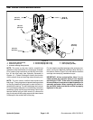
1. O--ring
2. Straight fitting
3. O--ring
4. O--ring
5. Straight fitting
6. O--ring
7. O--ring
8. Tee fitting
9. O--ring
Figure 80
2
3
6
8
9
1
5
7
4
3
2
7
LEFT WHEEL
FRONT
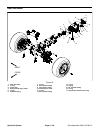
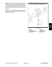
1. O--ring
2. Tee fitting
3. O--ring
4. O--ring
5. Straight fitting
6. O--ring
7. O--ring
8. Straight fitting
9. O--ring
Figure 81
2
3
6
8
9
1
5
7
4
RIGHT WHEEL
1
3
1
2
FRONT
Hydraulic
System


