


MODEL 2230R, Process Hydrogen Analyzer
Page 14
The user can change to another current range of the analog output in the field. Please refer to
the “I” command in Section 4.3 SERIAL COMMUNICATION.
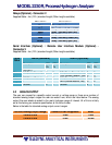
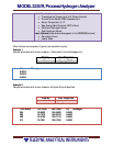
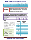
Below is the table for standard analog output voltage ranges:
Voltage Analog Output Range Power-On Self Diagnostic Error
0 V to 5 V
0 V
5 V
1 V to 5 V
0.5 V
0 V
0 V to 4 V
5 V
4.5 V
0.5 V to 4.5 V
0 V
5 V
The user can change to another voltage range of the analog output in the field. Please refer to
the “V” command in Section 4.3 SERIAL COMMUNICATION.
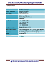
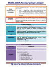
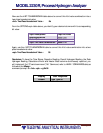
4.3 SERIAL COMMUNICATION
The user can monitor output and interface with the unit to perform calibration or adjust user
settings via the serial communication connector. The serial communication is accomplished via
an RS232 (optional RS422) interface.
Serial
Communications
Software
Any serial port two-way communications software such as terminal
emulators (HyperTerminal, Telnet, etc.) and purpose-built software
(using LabView, Visual Basic, C++, etc.) can be used to establish serial
communication with the unit.
Format and
Settings
RS232 (RS422 optional)
• 19200 Baud
• 8 bit data
• 1 stop bit
• No parity
• Xon/Xoff
Data Display
Streaming data is presented in column format. Once serial
communication is established and the unit is operating in normal
mode, data will be displayed in the user specified format. The display
output options are configured via a serial command as described in the
following sections (refer to the SERIAL COMMUNICATION COMMANDS,
FORMAT <fmt>, and OPTIONS <opt> sections). Columnated data
available are as follows:
WARNING: THE USER CANNOT CHANGE FROM A CURRENT RANGE TO A
VOLTAGE RANGE OR FROM A VOLTAGE RANGE TO A CURRENT RANGE
OUT IN THE FIELD. THIS REQUIRES A FACTORY MODIFICATION.